🖱️ Click to jump
1. What causes element distortion?
2. How to check the quality of items?
3. Criteria for checking the quality of finite elements4. How to prevent element distortion?5. Conclusion
We checked the model, the settings of the software package, and the calculation. On the surface, everything looks correct, but errors appear during the analysis. Familiar situation? Then this article is for you. Engineers often run into the same bugs.
It often happens that a non-linear calculation fails to converge after it has performed perfectly in the linear domain. Most likely, the problem is in the finite element mesh. Finite element meshing and control is an important step in finite element problem solving (FEM), and calculated results in FE tend to be most accurate when the elements are compact, without large elongation, skew, and deformation, which has been proven many times by experience.
What causes element distortion?
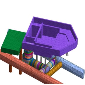
Element distortion can occur when describing a geometric irregularity. Using a higher density (number) of elements and a finer mesh size at these locations can help improve the accuracy of the calculation results and the quality of the mesh. However, using the same fine mesh size throughout the entire geometry is neither practical nor economical, since a larger mesh step is quite suitable for describing geometrically simpler parts of the model. Larger grid spacing is also applicable when the load application is sufficiently far from the region of interest, and the expected corresponding stress effect is trivial and causes little deformation. Therefore, for models that have both fine and coarse meshes, element distortion can occur due to changing the grid size. Figure 1 shows distorted elements due to the transition from large to small elements. They are highlighted in green.
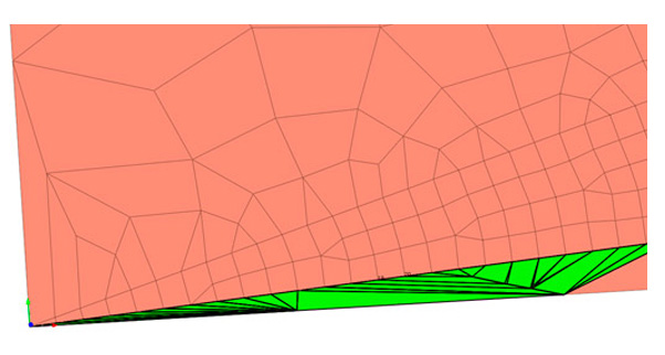 Figure 1_Distorted elements due to the transition from large elements to small ones
Element distortion can also occur due to the relationship between finite element mesh sets (Mesh Sets). In FEM, the connection of objects is provided with the help of nodal connections. Therefore, the easiest way to model two connecting objects is to merge the nodes at their connecting boundaries. However, when two sets of finite element meshes have different mesh sizes, mesh element transitions (transition elements) are required.
How to check the quality of items?
In addition to element distortion, the relative size between connected elements, the shape, and the quality of the finite element mesh has a greater influence on the calculation results than its absolute size: large or small. Therefore, after creating the meshes, it is important to check their quality and, if necessary, make changes.
In order to check the quality of the created finite elements in the software package, you need to call the appropriate tool. For example, in the midas GTS NX and midas FEA NX calculation systems, the tools for such a check are located along the following path: Mesh - Tools - Check - Check Mesh Quality.
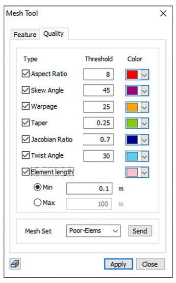 Figure 2. The dialog box for checking the quality of finite elements
Criteria for checking the quality of finite elements
1) Aspect Ratio
An aspect ratio is a ratio between width and length or the ratio of the longest side to the shortest side of a 2D element. For example, a square has the same width and length, hence having an aspect ratio of 1. As the shape deviates from that of a square, the aspect ratio gets larger. A value close to 1 is ideal - this ratio has a significant effect on the result of the calculation and, if the value is very large, it may be difficult to obtain normal calculation results, due to the fact that stress concentrations and other effects may occur in the elements.
For example, an element with an "Aspect Ratio" of 8 has the longest side eight times the shortest.
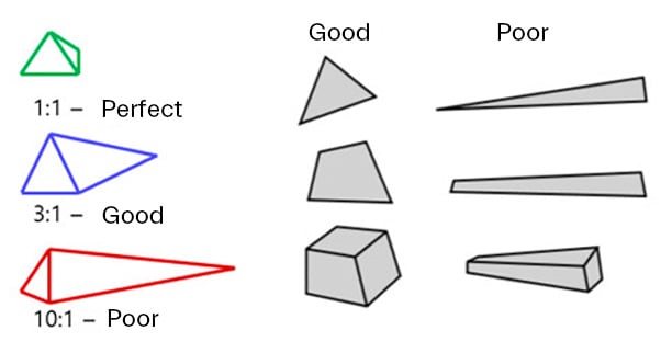 Figure 3. Finite element aspect ratio
2) Skew Angle
The slope angle describes how much the element's shape deviates from a rectangular shape (90 degrees) measured in angles. The quad forms an angle of 90 degrees, the Skew Angle is 0 degrees, this value increases as the shape deviate from the quad. For a solid element, the slant Angle is checked for each face, and the smallest value is selected as the slant angle. A value close to 0 is better. Figure 4 shows the Angle of inclination of triangular and quadrilateral elements.
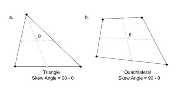 Figure 4. The angle of inclination for triangular and quadrilateral elements
3) Warp (Warpage)
Warping (skew) evaluates how much the shape extends beyond the plane. For a quad 2D element that has all nodes in the same plane, the value is 0. The value increases as the shape deviate from the plane. For a solid element, the warp is checked for each rectangular face and the smallest value is chosen as the warp value. A value close to 0 is better. This criterion affects the calculation result, and if the value is very large, it may be difficult to get correct calculation results. Figure 5 shows how warp is calculated.
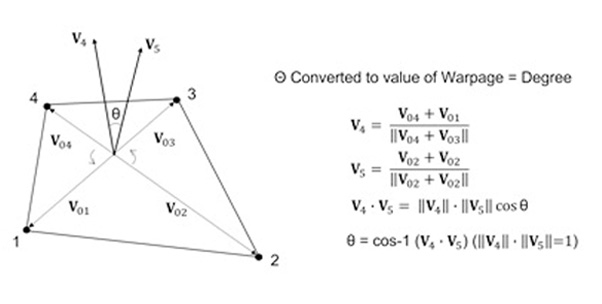 Figure 5. Determining the value of the warping criterion
4) Taper
This criterion geometrically calculates how much the quadrilateral deviates. Does not apply to triangular elements. The quad has a value of 1 and the value decreases as it deviates - meaning it gets closer to a triangular shape compared to its rectangular shape. For a solid element, the taper value is checked for each face and the smallest value is selected as the taper value. A value close to 1 is better. Figure 6 shows how to taper is calculated.
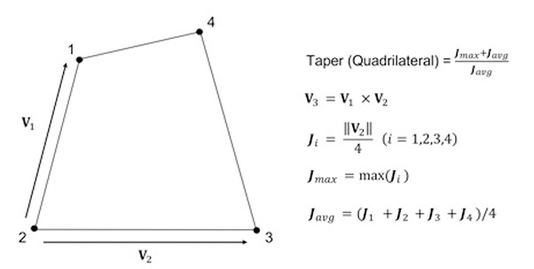 Figure 6. Determining the value of the taper criterion
5) Jacobian Ratio
The Jacobi determinant is calculated at each integral Gauss point on the finite element mesh. The Jacobi ratio is the ratio between the largest and smallest values of the Jacobi determinant (determinant). For 2D elements, the Jacobi determinant is calculated on the element projected onto the plane. For solid elements, the Jacobi determinant is calculated directly. If the quad is not convex, a negative value is an output and the calculation does not work properly. The Jacobi determinant must not be negative. Quadrilateral elements must be convex and the higher the value of the Jacobi ratio, the better.
In the two four-node elements shown below, element (a) is valid and element (b) is not.
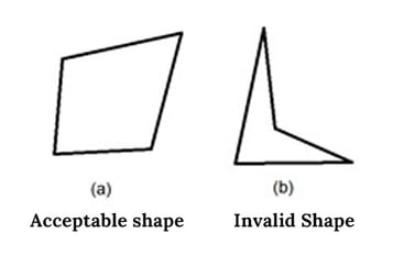 Figure 7. The acceptable shape of an element when evaluating the Jacobian Ratio criterion
6) Twisting (for solid elements) (Twist Angle)
A value that characterizes the twisting of two opposite faces of a solid element - one relative to the other.
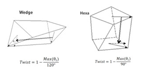 Figure 8. Twisting solid elements
For all six conditions above, midas GTS NX or FEA NX performs an automatic check and highlights items that do not meet the criteria specified by the user.
👇Online Training | Why Do You Need 3D Analysis: Comparison with 2D analysis
How to prevent element distortion?
To manage the finite element mesh in the software based on the finite element method, users are provided with a large number of tools to help customize and improve the quality of the finite element meshes.
For example, in midas GTS NX or midas FEA NX, there are tools: Mesh - Control - Size Control. Engineers can use this control and configuration tool before generating finite element meshes in one of three modes: Point, Edge, and Custom.
1) Point Mode
Specify the size of the elements around the selected point. The option is applicable only for points that belong to the surface or are internal objects. Points located on subforms (surface corners) are automatically ignored during finite element meshing.
For example, engineers can specify the size of features surrounding a selected point, as shown in Figure 9.
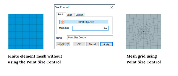 Figure 9. Finite element mesh control via size control - Point
2) Edge Mode
You can select faces (lines) and use one of the five methods described below to determine the position of mesh nodes on the selected faces (mesh size). The distance between nodes can be set directly, or the selected line can be broken by nodes into a given number of equal or variable (linear) length segments, as shown in Figure 10. This is especially useful at the boundary of the connection of several objects, where the use of finite element meshes is implied different sizes.
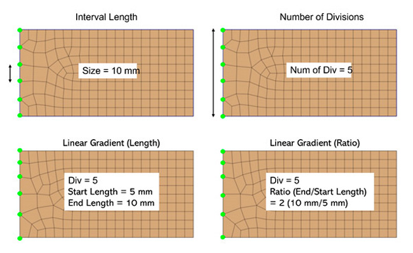 Figure 10. Finite element mesh control via size control - edge
- Fixed element size (Interval Length)
Specify a regular distance between nodes in the active unit system.
- Fixed Number of Divisions
Divides the selected line into several sections, according to the specified value.
- Linear Grading (Length)
Specify the distance between the start and end points of the line to automatically determine the location of the nodes by linear interpolation.
- Linear Grading (Ratio)
Specify the division factor (start/end) from the start to the end point of the line.
- Hyperbolic division law (Hyperbolic Tangent)
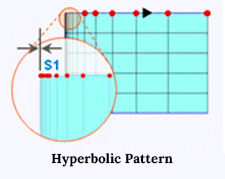
Specify the initial length of the element and the number of divisions to determine the distance between nodes, taking into account the total length of the line and the number of divisions.
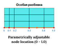
3) Custom Mode
You can specify the location of nodes on a selected face by directly specifying node coordinates in tabular form. Setting the coefficient in the range from 0 to 1 allows you to automatically calculate the position of the node on the selected line.
Thus, the engineer can fully control both the quality of the generated finite element meshes and the process of their generation, which will eventually lead to a high-quality finite element mesh in the calculation model and, as a result, to high-quality calculation results.
Finally
Often there are cases when a fine mesh is needed around structural objects or in the area where you need to analyze the results of the calculation in detail. For example, significant movements and stress changes are expected around a load application, or the moment value may be high along part of a beam element of some structure. To save resources and time, it makes sense to generate a fine finite element mesh only near the specified areas, and describe the rest of the model array using a coarser mesh. The mesh control described above can be implemented to connect the fine and coarse meshes, which model the merged nodes at the boundaries of the mesh set, and smooth element size transitions to prevent element distortion.

⭐ Recommendation (Click)
- Blog | 2D vs 3D Approach- Finite Element Analysis(FEA)
- Blog | The Advantages Of 3D Analysis In Major Fields
👉 Relevant project (Click)
- Blog | How To Define The Construction Sequence
- Blog | Design Of 20m Deep Excavation With Permanent Anchored SBPW and CBPW