Design of 20m Deep Excavation with Permanent Anchored Secant Bored Pile Wall (SBPW) and Contiguous Bored Pile Wall (CBPW) as Retaining Structure of Cut and Cover Tunnel
🖱️ Jump to the contents (Click)
1. Introduction
3. Ground Improvements4. Lateral Earth Support System and Ground Improvements5. Measurement Program for Excavation6. Finite Element Simulations and Model Parameters7. Finite Element Simulations Results8. Conclusion9. Bibliography
Introduction
The design of deep excavation of cut and cover tunnel for Portal of Konak Tunnel in the Konak Square
in İzmir, is presented. Nowadays the excavations of cut and cover tunnel have been started. The cut and cover excavation area is approximately 60m x 42m and is shown in Figure 1. The maximum height of the critical excavation section is 20 m. At the right side of the excavation section with maximum height, an adjacent 5 storey masonry museum building is located and shown in Fig 2.
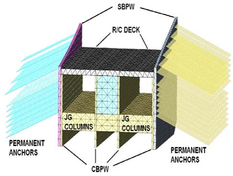
The groundwater level has been observed in the excavation area underground surface. For the staged excavation of cut and cover tunnel structure, 1000 mm diameter secant bored pile (SBPW) walls are designed at the outside boundary of excavation. At the inner side 1200mm diameter contiguous bored piles (CBP) with the center to center spacing of 1600 mm and reinforced concrete deck are designed as components of a portal structure.
SBPW and CBPW are supported with permanent soil anchors. Before the start of the excavation, jet grout columns are designed at excavation basement level for stability against heave and under nearby structure foundation against settlements.
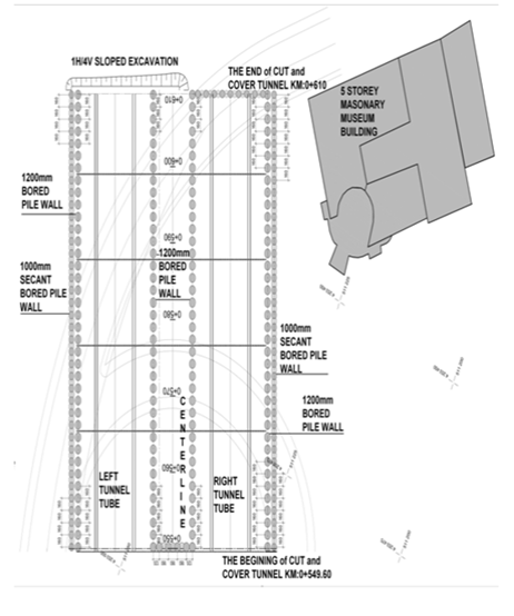
Figure 1. Cut and cover structure plan, secant, and bored piles application plan
The stability of cut and cover tunnel, displacements closed the excavation, internal forces in retaining walls and settlements under nearby structure foundations are computed using PLAXIS 2D, MIDAS 3D, and SAP2000 finite element simulations.
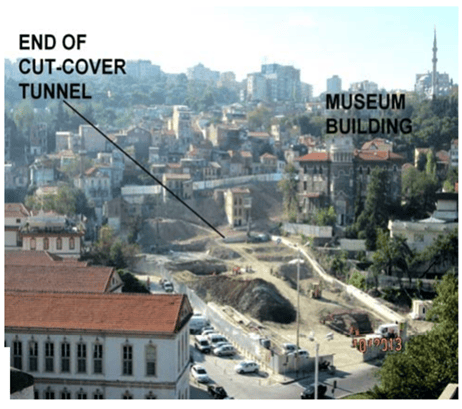 Figure 2. Excavation Area
Site Description
The original site investigation comprised a series of 14 deep borings is opened within the excavation area and footprint of the existing museum building. In-Stu tests were performed both conventional SPT blow count and pressuremeter test. There was a limited program of laboratory tests (index properties, water content and UU strength testing in the clay, and particle size distributions for the granular layers) while permeability properties were reported from lugeon tests.
Figure 4 summarizes the soil profiles, lateral earth support systems, and ground improvements for the most critical excavation cross-sections
included existing masonry museum building. The subsurface profile comprises 1m - 2m of uncontrolled fill material overlying the medium stiff and stiff clay layer on sedimentary claystone, sandstone and siltstone bedrock layer.
The bedrock was described as very weak to weak, completely to slightly weathered rock according to pressuremeter test results, net limit pressures PL* = 8.3 - 38.5 kg/cm2 for very weak PL* = 15.4 - 61.1 kg/cm2 for weak rock. RQD values of rock varies between RQD = 0% - 64%
The clay deposits range in consistency from a medium-stiff to stiff and corresponding undrained shear strengths from UU tests, su= 45kPa to 163kPa, respectively. The clays are lightly overconsolidated, but no consolidation tests were performed for this project. In the longitudinal profile of the excavation plan and in some cross-sections, sand and gravel layers were found, lying between clay and rock layers.
These sand and gravel layers contain pressured water and they have relatively high permeability values, k = 1.2 m/day according to index properties with literature assessments. The blocky, gravelly sand layers were classified as very dense layers based on SPT data. Groundwater conditions were measured by a series of piezometers, within the underlying sands, till and rock layers and all borehole observations. These data consistently confirm the groundwater observation at below the ground surface level.
The masonry museum building, immediately adjacent to connection of the east piled wall row and the beginning of excavation tunnel as shown in Figure 3. The museum building is founded on an uncontrolled fill overlying clay layer without any areal mat or strip foundation. The building is founded on separate under-column and wall footings.
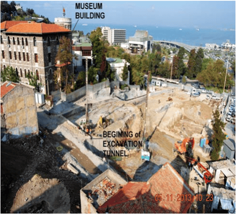 Figure 3. Museum Building
So this foundation is unexpected to distribute the ground movements and hence, is most likely to suffer serious damage during excavation to the building.
Ground Improvements
Changes in groundwater level can lead the unexpected effective stress increments and it could be the result of unwanted consolidation settlements under masonry museum building founded on uncontrolled fill and underlying clay layer and the surrounding other structures foundation.
For the purposes of prevention in changes groundwater level under museum building and surrounding structures foundation in the city center, 80 cm diameter and 10 cm overlap intersecting with 5m and 7m thick jet grout columns were designed at the base elevation of excavation shown in Figure 4.
Whereby the movement of groundwater and the possibility of basement heave were prevented against excavations under groundwater level.
Another useful of jet grout columns in the excavation basement level is to behave such an embedded pressure element (strut) and to prevent the base deformation of wall elements, the possibility of kick of failure of the system and then close the frame structure with reinforced con[1]cret top deck.
For the purposes of increasing the shear strength of museum building foundation soil and preventing displacements that can be caused by excavations, soil improvement was designed with consolidation and jet grouting.
Lateral Earth Support System and Ground Improvements
For the permanent lateral earth support system of cut and cover tunnel, 1000 mm diameter secant bored pile walls (SBPW) are designed at outside boundary of excavation. At the inner side, 1200 mm diameter contiguous bored piles walls (CBPW) with center to center spacing of 1600 mm and reinforced concrete deck are designed as components of portal structure. In the most critical excavation section, walls supported with ten levels of post-grouted soil anchors were designed to resist the lateral earth and pore water pressures, seismic loads, and surcharge loads from construction equipment and adjacent structures.
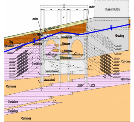
Figure 4. Idealized soil profile, support system, and ground improvements
The tieback anchors were also specified with zero tolerance against water leakage in order protects the steel tendons from long-term corrosion problems according to FHWA-IF-99-015, 1999 and CIRIA C580, 2003. Each anchor was inclined at 20° with mini[1]mum fixed anchor lengths of 10m in the bond soil and weak rock zone. Horizontal spacing of the anchors ranged from 0.80m to 1.6m and each tendon comprised from 3 strands of 1.5cm diameter high tensile strength steel. The vertical distances of anchors are 2m.
The lock-off loads for each level of anchors around the excavation are designed as 35 tons. It should be noted that the two levels of anchors just below and above the reinforced deck are the most critical levels and this region anchor's horizontal distance is designed as 0.8m.
Measurement Program for Excavation
The excavation performance of the Konak Tunnel cut and cover structure of all excavation sections will be monitored by topographic measure points and tiltmeters of museum building set[1]tlements. The deflections of SBPW and CBPW will be monitored by readings from a series of incli[1]nometers. The pore-water pressures in soil and weathered rock and groundwater level changes during excavations will be monitored by vibrating wire piezometers. Axial forces in the post-grouted pre-tensioned anchors will be monitored by load cells in all anchor levels.
Finite Element Simulations and Model Parameters
A series of finite element simulations have been carried out to obtain better insight into the performance of the excavation support system for the Konak Tunnel cut&cover structure excavation.
The deformation calculations and the performance of lateral support systems and deformation-based calculations have been carried out with all using the plane–strain models in PLAXIS 2D and 3-D continuum models in MIDAS 3D finite element package programs.
The large number of prepared finite element 2D and 3D models for excavation cross-sections represent the behavior of all sides of the excavations. The other interesting point in this project design stage, modeling the structural behavior of SBPW, CBPW and RCD frame system. Because the structural modeling of adjacent SBPW and CBPW piles is required to define imaginary constrained elements to interface surfaces of walls in numerical models. In this way it is possible to catch real bending behavior of both pile walls together.
For this purpose the structural design of reinforced concrete SBPW, CBPW and deck was designed with using SAP 2000 finite element models.
The finite element model representing the behavior of lateral support systems and defining the displacement levels that will occur due to excavation is given below in Figure 5., Figure 6., Figure 7., Figure 8. and Figure 9. The staged construction modeling of excavation was modeled in more than 30 stages in PLAXIS 2D and MIDAS 3D.
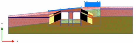 Figure 5. PLAXIS 2D finite element model
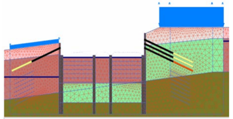 Figure 6. PLAXIS 2D finite element model at 14th. stage
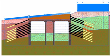 Figure 7. PLAXIS 2D finite element model at 30th. final stage
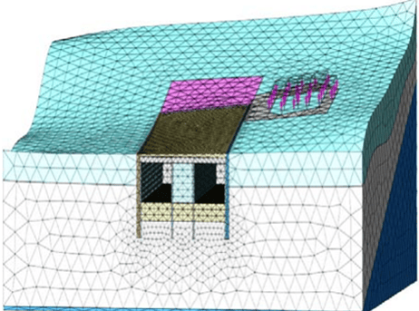
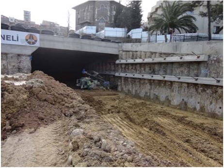
The excavation in Konak Tunnel cut and cover tunnel have been started recently. The recent construction stages are shown in Figure 10., Figure11. and Figure 12. below.
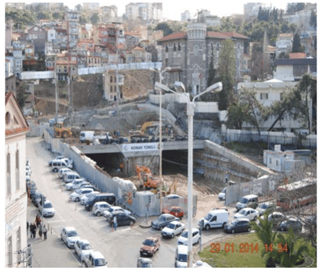 Figure 10. Excavations under cut and cover structure
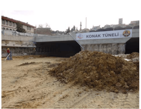
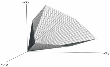
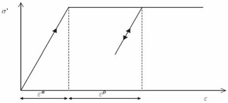
Soil deformation parameters and shear strength properties was selected according to index properties and UU test results from boreholes samples, pressuremeter test results and literature survey of similar site properties. Each of the soil layers have been simulated using the Mohr – Coulomb model due to lack of parameters for hardening soil model. The stress and strain relations of Mohr – Cloumb model are given below in Figure 13. and Figure 14.
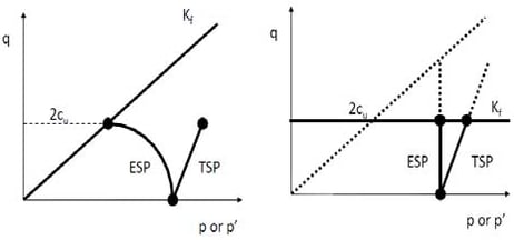
For clay layer, undrained behavior was defined in PLAXIS with Undarained-B loading for using UU test results in analyses. The stress path is given below in Figure 15. for Undrained B loading in PLAXIS 2D.
The shear strength and elastic properties is characterized for very weak rock overlying weak rock layer for drained loading condition such an assuming dense sand layer. For weak rock layer shear strength properties was assessed from RMR rock classification system. The drained elastic parameters for input were defined from using the relation given by according to relation between over consolidation ratio OCR, plasticity index and Eu/su by Duncan and Buchignani, 1976 in Figure 16.
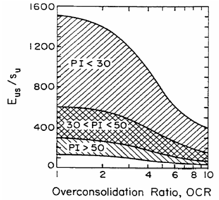 Figure 16. Eus/su versus OCR
The drained elasticity modulus is assessed using Equation 1:
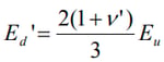
where v is the drained Poisson ratio and Ed’ is the drained elasticity modulus. The elasticity very weak rock layer is selected from the table given by Bowles.
The elasticity modulus of the weak rock layer is defined by using Equation 2: given by Hoek, Torres, Corkum, 2002.
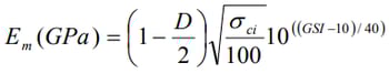
where σci is the uniaxial compressive strength of rock sample, GSI is the geological strength index, D is the disturbance factor and Em is the rock mass elasticity modulus.
The model parameters assumed in finite element models are given below Table 1.
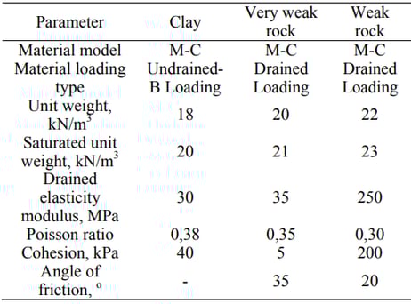 Table 1. Model parameters in finite element models
The elasticity modulus of jet grout columns was defined as Ejg=500 MPa by using the table given by Durgunoglu, 2004. The grid spacing of jet grout columns was assessed for wanted elas[1]ticity modulus for silcrete elements by using the relation given by Saurer et all. 2011.
Finite Element Simulations Results
The initial settlement of museum building before the start of excavation was calculated as 3.5 cm given below in Figure 17. This back analysis result value is consistent with the building investigations. Also, some differential settlement cracks were observed on museum building walls in site investigations.
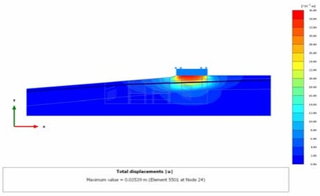
Figure 17. Initial settlements of museum building before the start of excavations, PLAXIS 2D
The most critical level was the excavation stage under the reinforced concrete deck. This stage is fourteenth stage of the model and fourth anchors level of construction. At this level, maximum total displacements were obtained as 6.5 mm at the nearest corner of foundation to excavation border is given in Figure 18.
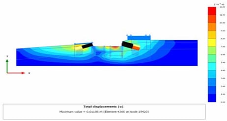 Figure 18. Settlements of museum building at fourteenth stage, fourth anchor level, PLAXIS 2D
In this stage of excavation, the maximum wall deflections of SBPW and CBPW walls was calculated as 7.3 mm is shown in Figure 19.
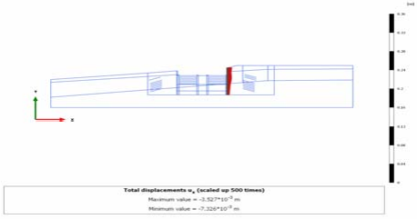
Figure 19. Horizontal displacements of SBPW and CBPW elements at fourteenth stage, fourth anchor level, PLAXIS 2D
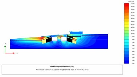
In the final stage of excavation, maximum total displacements were obtained as 1.0 cm at the nearest corner of foundation to excavation border given in Figure 20.
In the final stage of excavation, the maximum wall deflections of SBPW and CBPW walls were calculated as 7.3 mm as shown in Figure 21.
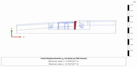
Figure 21. Horizontal displacements of SBPW and CBPW elements at final stage, tenth anchor level, PLAXIS 2D
According to the 3 dimensional Midas 3D analysis results, at the final stage, the maximum total displacements were obtained as 1.3 cm under the museum building foundation given in Figure 22.
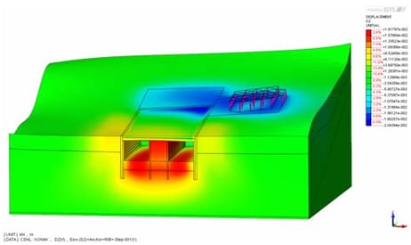 Figure 22. Settlements of museum building at final stage, tenth anchor level, Midas 3D
In the final stage of excavation, the maximum wall deflections of SBPW and CBPW walls were calculated as 7.1 mm as shown in Figure 23.
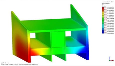
Figure 23. Horizontal displacements of SBPW and CBPW elements at final stage, tenth anchor level, MIDAS 3D
The structural model, the obtained deformation curve, bending moment diagram of cut and cover structure from SAP 2000 analyses are given below in Figure 24., Figure 25. and Figure 26.
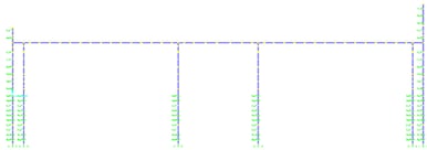 Figure 24. SAP 2000 structural finite element model
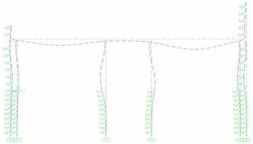
Conclusion
Konak Tunnel is one of the major transportation projects in Turkey. The project area is located in the city center of İzmir. The adjacent buildings to the excavation area, high groundwater level, traffic density, and the urgency of the project are the major difficulties.
Deep excavations for the Konak Tunnel cut and cover structure were designed to support by a permanent lateral earth support system comprising a 1000 mm diameter SBPW and 1200 mm CBPW, reinforced concrete deck and up to 10 levels of prestressed post grouted against corssion protected soil anchors.
Before the start of the excavation stages, the ground improvements systems as jet grout columns and grouting were designed to prevent and mitigate the changes in groundwater level and deformations.
According to analysis results, the lateral earth support system was very successful in controlling lateral wall movements of walls and total displacements that may occur under museum buildings.
The 2D and 3D analysis results are in good compliance. The results show that the final stage of excavation the maximum wall deflection is about 7.3 and 7.1 mm. And under museum building, the maximum total displacement is 1 and 1.3 cm. These values show that the settlements values of both wall and museum building foundation soils are within expected and acceptable ranges.
Analysis results also show that designing jet grout columns under the excavation basement layer and soil improvement under the museum building prevent and mitigate the changes in groundwater level. The permanent pre-tensioned anchor loads remain under design lock loads in all excavation stages. The reinforced concrete design of walls and deck was made within reasonable limits.
But it should be remembered that these analysis results are not confirmed from field instrumentation data. The excavation in the Konak Tunnel cut and cover tunnel has been started recently. The analysis will be verified by the detailed instrumentation results.
Bibliography
Bowles, J. E. ;.2005. Foundation Design and Analysis, Fifth Edition, The Mc-Grawhill Company Inc.
CIRIA C580 ; 2003. Embedded Retaining Walls Guidance for Economic Design, London.
Hoek, E. ; Carranza, C. ;Torres & Corkum, B. 2002. Hoek-Brown Failure Criterion-2002Edition. In: Proceedings of the NARMS-TAC Conference on Soil Mechanics and Geotechnical Engineering. Toronto
Holtz, R. D. ; Kovacs, W. D. ; Sheahan, T. C. 2011. An Introduction to Geotechnical Engineering, Second Edition, The Prentice Hall Company Inc.
Midas / GTS. 3D Finite Element Code, 2012. Getting Starting Manual.
Midas / GTS. 3D Finite Element Code, 2012. Analysis Case Manual.
Plaxis 2D Finite Element Code, 2012. Material Models, Netherlands.
Plaxis 2D Finite Element Code, 2012. Reference Manual, Netherlands.
Sauer, E. ; Marcher, Th., T.B. ; Lesnik, M. 2011. Grid space optimization of jet grouting columns. In: Proceedings of the 15th European Conference on Soil Mechanics and Geotechnical Engineering. Netherlands: IOS Press
Temelsu International Engineering Services Inc. 2012. Konak Tunnel and Connection Road, Konak Portal Geological Study Report . Ankara.
Temelsu International Engineering Services Inc. 2013. Konak Tunnel and Connection Road, Konak Portal Final Design Report . Ankara.
U.S.Department of Transportation Federal Highway Administration;1999. Geotechnical Engineering Circular No.4, Ground Anchors and Anchored Systems, Washigton.


👇 Watch the popular case study webinar
How to quickly master the geotechnical design report