The most common cases to consider 3D effects in tunnel design
In practice, different design methods are used in solving geotechnical problems depending on the type of issue such as the tunneling, braced excavation, or bearing capacity of a foundation, that is, the basic mechanism of the design method differs depending on the problems even for the same ground.
This post focuses on general cases of tunnel construction under three-dimensional (3D) conditions.
01. Influence of tunnel construction on existing tunnel or structure
The development of a comprehensive and efficient underground public transport system is the key to a sustainable transport system. This has resulted in many tunnels being built in densely urbanized areas and at close proximity to buildings and infrastructures. Tunneling in the dense urban areas frequently results in crossing or bypassing the existing tunnels. It is obvious that the crossing tunneling will adversely affect and even damage the existing tunnels if the induced deformation exceeds the capacity of tunnel structures.

Crossing tunneling on the existing tunnel
The tunneling effects on adjacent structures can be detrimental as problems such as pile settlement and passive loading on the piles could arise. Thus, the prediction of the effect of tunneling on the existing tunnel and structure becomes an important issue in the planning, designing and construction process of new tunnels.

Tunneling effect on adjacent pile foundations
▪️ Blog | Metro Station Pankrac - Modelling and Analysis in Midas GTS NX
▪️ Project Stories | Interface between new railway tunnel and subway extension tunnel
▪️ Project Stories | Construction of the two level road interchange near the metro tunnel
02. Shaft connection / Cross passage
The design of shaft-tunnel junctions has evolved over time. Initially, the junction between shafts and the bored tunnel was achieved by excavating the cross-passages in artificially frozen ground. Later, the technique of artificial freezing was replaced by a ground improvement approach using plastic concrete. More recently, a new concept was introduced whereby no ground improvement and no connecting galleries are necessary. The principle lies in driving the TBM to partially intercept an unexcavated circular slurry wall. The shaft can then be excavated in several stages, allowing for the construction of the upper part and the lower part of a reinforced concrete portal aimed at strengthening the opening created by the TBM in the shaft slurry wall.
Advanced 3D numerical modelling is thus used to assess structural forces on which the detailing is based. The complex geometry of the junction associated with the non-linear behaviour of the ground and of the inter-panel joints as well as the impact of the construction sequence led to adopt advanced numerical methods. It is only recently that finite element software with sufficient capabilities and user-friendliness are available to model such a 3D configuration in a realistic way and within a timeframe compatible with project requirements.

Vertical shaft with the connection tunnel

3D rendering of SCL shaft, cross passage and tunnel
▪️ Project Stories | Construction of the sprayed concrete lining (SCL) lift shaft, adit tunnel and cross passage▪️ Project Stories | Ground support of station caverns and shafts
03. Curved tunnel trajectories
More and more people use CAD program for modelling infrastructure projects, especially tunnels and bridges. Therefore, the geometry modelling capability of numerical analysis can be challenging to use for modelling linear infrastructure in reference to alignments and more complex 3D geometry. For example, a tunnel or bridge often has curved alignments, longitudinal inclination, widening and narrowing or cross fall.

Curved tunnel in nuclear waste disposal facility
04. Tunnel advanced core reinforcement (Auxiliary construction methods)
During the tunnel excavation, the most important problem is the stability of the tunnel face. The collapse of this one induces serious consequences on both the safety and the financial plan. The umbrella arch is a temporary support system forming a structural umbrella from the insertion of an assortment of longitudinal support members installed from within the tunnel, above and around the crown of the tunnel face. The umbrella arch is often considered a pre-support technique as the support members are installed prior to the first pass of excavation. In this manner, the umbrella arch provides support to the ground ahead of and at the working face as well as the unsupported span immediately behind the working face, inside the tunnel. The latter is a primary distinguishing feature and benefit of the umbrella arch in comparison to other pre-support techniques, such as fiber-glass dowels (i.e. face bolting), which may be used in combination with the umbrella arch. Therefore, 3D modelling of these tunnels and their reinforcement is essential to predict surface settlements and an important tool to validate appropriate tunnel designs.

Temporary structural support (forepoles; steel sets (i.e. H-piles); shotcrete; and rockbolts)

Steel Pipe Grouting (Umbrella reinforcement)
05. Portal design of mountain tunnel
Tunnels located in mountainous terrain have to enter and exit the mountainside through portals. A tunnel portal, being at the transition zone between surface and underground construction, must therefore consider the technical aspects of both slope stability and tunnel stability. Since the portal area is near the surface, the ground is usually more weathered, requiring more intense ground support than in deeper less weathered zones. Therefore, it should be reviewed the influence of topography, rock type, and rock structure upon tunnel portal stability and design. In addition it considers tunnel variables such as tunnel size, tunnel opening geometry, pillar width for parallel tunnels, as well as the risks of landslide, rockfall and avalanche at portals.

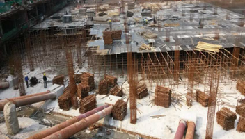
Tunnel portal construction site
Click here to see the case study webinar 👇