🖱️ Jump to the contents
1. What is excavation work?
2. Type of Retaining Wall3. The Construction Stage of Retaining System
4. FEM Analysis for Retaining System5. Other Calculations for Retaining System
👇 Watch the popular case study webinar
How to quickly master the geotechnical design report
What is Excavation Work?
1-1. Introduction
In construction terms, excavation work generally means work involving the removal of soil or rock from a site to form an open face, hole, or cavity, using tools, machinery, or explosives. Excavation work can occur anywhere such as construction sites, business premises, and public areas. Excavation work includes open excavations, potholing, pit excavations, trenches and retaining walls, shafts, and drives.
1-2. Type of Excavation
Open excavation in open ground is an open excavation and can vary in shape and size.
 Figure 1. Open excavation
Potholing is usually a small excavation or inspection hole to find underground services.
 Figure 2. Potholing
 Figure 3. Pit excavation
When a retaining wall is built, an open excavation becomes a trench formed by an excavated face on one side and a retaining wall on the other. Usually, workers need to access this trench to work.
 Figure 4. Trenches
A trench is a long narrow excavation that is deeper than it is wide, and open to the surface along its length. Trenches are generally excavated to install or maintain underground services or to investigate what is beneath the surface.
 Figure 5. Retaining Walls
Sinking a shaft involves constructing a vertical excavation with access and spoil removal from the top. Drives are small openings cut into the sides of trenches or shafts or elsewhere, for example, under roads. Cutting a drive is particularly hazardous as it introduces the risk of trapping workers with no alternative escape route. Shafts and drives are often constructed to provide access or ventilation to a tunnel. Shallow shafts can sink for investigating or constructing foundations, dewatering, or providing openings to underground facilities.
 Figure 6. Shaft
1-3. What we are doing
The speed of an excavation collapse increases the risk associated with the type of work. The consequences are significant as the falling earth can bury or crush any person in its path resulting in death by suffocation or internal crush injuries.
Hence, geotechnical and structural engineers need to be verifying the safety works for this construction prior to excavate down and share the proper design(drawing) to the construction site.
Type of retaining wall
2-1. Diaphragm Wall (D-Wall)
A diaphragm wall is a structural concrete wall constructed in a deep trench excavation, either cast in situ or using precast concrete components. Diaphragms walls are often used on congested sites, close to existing structures, where there is restricted headroom, or where the excavation is of a depth that would otherwise require the removal of much greater volumes of soil to provide stable battered slopes.
Diaphragm walls are suitable for most subsoils and their installation generates only a small amount of vibration and noise, which increases their suitability for works carried out close to existing structures. In addition, floor slab connections and recessed formwork can be incorporated into the walls.
The high cost of diaphragm walls can make them uneconomic unless they can be incorporated into part of a building structure. As such, they are suited for deep basements, underground car parks, and rail stations, tunnel approaches, underpasses, deep shafts for tunnel ventilation, pumping stations, and so on.

Figure 7. Diaphragm wall
>> Related Project Stories
- Anchor block stability of the abutment foundation
- Evaluation of the effects induced on sensitive buildings during the excavation of two TBM tunnels
- Deep excavation in a sloping site for the assessment of induced ground movements
- Influence of excavation foundation pit on existing tunnel
2-2. Contiguous Bored Pile Wall (CBP Wall)
Contiguous pile walls are installed using rotary bored or CFA techniques. This type of retaining wall is constructed with spaces between adjacent reinforced concrete piles and is used on a range of engineering or building projects including but limited to road or rail underpasses, underground shafts/tanks, cut and cover tunnels/portals or basements.
Contiguous piled walls are used in dry and cohesive soils and are often the quickest and more economic method of constructing retaining walls. In certain ground conditions, it may be necessary for the design to incorporate temporary props or ground anchors to provide additional lateral support to the wall.
These can be used for more flexible geometry than a diaphragm wall and are suitable for ground conditions where there is no requirement to exclude groundwater and vertical loads can be carried by the wall piles. Contiguous piled walls are suitable and easier to build in load variations as well as minimizing installation time, with no requirement for a guide wall.

Figure 8. Contiguous Bored Pile Wall
2-3. Secant Bored Pile Wall (SBP Wall)
A Secant Piled Wall is a retaining wall constructed for ground retention prior to excavation. The wall is formed by constructing alternating primary and secondary piles where the secondary piles are partially cut into either side of the primary piles in order to form a continuous impervious structure.
Secant walls are frequently used as an alternative to Diaphragm walls where obstructions are anticipated, or in urban basement projects where space is limited. In comparison to diaphragm walls, they can be flexible in shape and offer a relatively compact operation in comparison to the equipment required to support bentonite holding and circulation equipment.
There is minimal vibration, low noise levels, and the flexibility to fit complex site boundaries and maximize land use. Secant piling can also go through underground obstructions such as steel, heavily reinforced concrete, granite, and masonry while, at the same time, avoiding any risk of construction-induced settlements to neighboring structures.

Figure 9. Secant Bored Pile Wall
2-4. Sheet Pile Wall
Sheet pile wall is generally thin piles. They make plates of concrete, timber, and steel. These piles are driven into the ground for either separating members or for stopping the seepage of water, they are not meant for carrying the vertical load.
Sheet pile wall provides high resistance to driving stresses and has lightweight. It can be used on several projects and has log service life above or below water with modest protection. It is easy to adapt the pile length by either welding or bolting.

Figure 10. Sheet Pile Wall
The Construction Stage of the Retaining System
Currently, the construction industry emphasized the timely delivery of the projects whether it be any infrastructural developments, residential & commercial building structures, or any other civil works. There are two methods to carry out the excavation works generally used on the site currently: bottom-up and top-down.
3-1. Bottom-Up Approach
| Advantages | Disadvantages |
|
- Design is easier and therefore design costs are lower than the top-down approach. - Waterproofing can be installed around the whole outside, including the outside the permanent walls. - when the excavation is not wide then this approach is quicker than the top-down approach. |
- Construction is usually slower and more expensive than the top-down approach. - Temporary decks need for taking the heavy capacity from the crane. - For very deep excavation, the retaining wall size will be required larger than the top-down approach - The temporary walls serve little or no purpose after completion and, therefore, are wasted. |
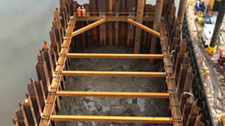
This conventional method involves first casting temporary retaining walls to the required depth below ground, digging and removing soil, installing temporary steel strutting, and then creating the complete hole with a base slab. The building work then rises from the base slab. Necessarily, there is taking a long time during the excavation in which construction cannot take place.

Figure 11. Bottom-Up Method
3-2. Top-Down Approach
| Advantages | Disadvantages |
|
- This offers very quick site coverage which includes a robust working platform. - Requires little or no temporary steel shoring producing good cost savings. - Multiple accesses are made possible through the voids in the slab and not limited to around the perimeter. - Cheaper to construct. |
- Access is only via. the openings below the slabs during the excavation. - For high-rise buildings, this approach requires strong foundations and columns. |
The project begins by casting the retaining walls with central supporting ‘kingpost’ columns (if, necessary), and then excavating enough of the earth to complete the first slab on the ground surface. This slab is substantial enough to take the weight of construction equipment including cranes and incorporates an opening through which soil can be lifted and removed. The excavation then takes place under the first slab, and the next permanent slabs are cast on the way down to the desired depth. This is ideal for high-rise structures in constrained sites and can result in time savings that can amount to several months. Cost savings are available too because generally no steel strutting is required for the wall support.
Top-down construction uses the permanent structure(slabs) to strut as the excavation is taken down in stages, slab by slab. Another use of the top-down approach is when constructing new metro lines under the roads. In these cases that it’s possible to use the top slab to safely carry all utilities and some of the roads can be reinstated until the works underneath have been completed.

Figure 12. Top-Down Method
FEM Analysis for Retaining System
Currently, the FEM analysis method is often to carry out for safety checking of the retaining system from excavation works, and prediction from FEM analysis is closer to real estimate than before due to the development of the FEM program.
4-1. Consideration
When geotechnical engineers are carrying out the FEM analysis, it should be considered a real condition of the site and get the full information to make the proper model.
First, Soil parameters are defined by in-situ test, laboratory test and others related to soil parameters and soil layers will be defined by borehole log data. For the soil layer, it needs engineering judgment to make a more realistic or conservatively, or tightly.
Second, geotechnical engineers are considering the water condition to take the pore pressure. It is also gained from borehole log data. From my experience, if the water level is higher then, the deflection of the retaining wall is higher, and ground settlement is lesser.
Third, it is engineering judgment also to consider the boundary condition and element size of the model. Generally, it is considering the small size of elements nearby the structures or somewhere where it needs to verify and the rest part can be used larger size of elements where I don’t need to check.
Lastly, it is necessary to consider the loads on the ground surface as a surcharge. It will be affected to the settlement of the ground surface, deflection of the retaining wall, and behavior of existing structures such as adjacent buildings and underground services.

Figure 13. FEM Analysis
4-2. Result Verification
From the result, geotechnical engineers need to verify the displacement of the ground and structures. If your excavation area is close to existing buildings and underground structures. You need to do the damage assessment for them to make them stable. It should be considered alternative design and construction process when the results are over than the requirements.
For displacement(settlement) of the ground, if you have allowable settlement and get the result which is over then that. You need to check again the water level whether it is lower position than borehole log data and surcharge location and amount whether it is correct first. If your water level and surcharge are correct, you will get less settlement considering the increased size of strutting and retaining wall or give the preload on your strutting based on your axial force result. Also, you can propose ground improvement(grouting) nearby the excavation area.
Deflection of the retaining wall is corresponding to ground displacement(settlement). They are moving together generally so that solution above will be helpful to get the proper(lower) deflection of the retaining wall.

Figure 14. Displacement result
Structural results also can be verified by the geotechnical engineer as well.
If your excavation model is contained retaining walls and struts. Retaining walls and struts are assumed by beam and truss elements respectively. Basically, you can get the bending moment and shear force result from the beam element and axial force from the truss element.
For your retaining wall which is assumed by beam element, there are two reinforcements in there; main rebar and shear link. The main rebar will be calculated by bending moment result considering the P-M curve and the shear link will be calculated by shear force result. For your strut which is assumed by truss element, it will be calculated by axial force considering section member (size), length, angle, spacing, buckling, and others related to checking the structural capacity.
So, you can propose the section member of the supporting system to the construction site with your FEM analysis results considering above.

Figure 15. Force Result
Other Calculations for Retaining System
5-1. Teo-in depth
Toe-in stability check shall be carried out to determine the toe-in depth or embedment of the retaining walls to ensure that adequate passive resistance can be mobilized. It will be calculated based on the bending moment of the soil and water pressure from the active and passive sides.

Figure 16. Teo-in Depth Checking
5-2. Base Stability
Base stability check shall be carried out to ensure that there is an adequate factor of safety against base failure in soft clay. Base stability checking shall be carried out not only for the final stage of excavation but also for intermediate stages where layers of soft clay exist between the ground and final excavation level.
If a stiff retaining wall is embedded into the soil below the excavation depth, the modified Terzaghi method shall be used to calculate the factor of safety.

Figure 17. Base Stability

Figure 18.Equation
5-3. Hydraulic Uplift
Hydraulic uplift checking shall be carried out to ensure that base of the excavation would not “blow out”. This checking shall be carried out in accordance with the below. The minimum factor of safety is defined in the below equation.

Figure 19. Hydraulic Uplift
Where necessary and appropriate, hydraulic uplift must be checked for intermediate levels to ensure that there is an adequate factor of safety. Any development of pore pressures as the excavation progresses shall also be continuously monitored.
Where necessary and appropriate, relief wells shall be used inside the excavation. The design shall also check for piping, where appropriate. This check shall be based on seepage analysis of the section such that the seepage force is less than the effective unit weight of the soil. The seepage force is equal to the hydraulic gradient times the unit weight of the soil.
Conclusion
There are so many methods and formations to check the safety of the condition for excavation work and they are not 100% sure. You need to approach them with engineering judgment to verify safety works and find the way to get whether it is technically feasible.


>>Reference:
“Civil design criteria for road and rail transit systems”, Chua Swee Foon, Francis Tam. Feb. 2008.
“Excavation safety[Website]” (2021, Aug. 26). https://www.worksafe.govt.nz/topic-and-industry/excavation/excavation-safety-gpg/
“Digging deeper and smarter[website]” (2021, Aug. 26). https://aecom.com/without-limits/article/digging-deeper-smarter/
“Everything about sheet-pile walls[Website]” (2021, Aug. 26). https://civilengineeringbible.com/article.php?i=10
“Secant Retaining Walls[Website]” (2021, Aug. 26). https://www.bacsol.co.uk/solution/secant-piled-wall/
“Contiguous Retaining Walls[Website]” (2021, Aug. 26). https://www.bacsol.co.uk/solution/contiguous-retaining-wall-piling/
“Diaphragm wall[Website]” (2021, Aug. 26). https://www.designingbuildings.co.uk/wiki/Diaphragm_wall
“Top-down construction method[Website]” (2021, Aug. 26). https://www.geotech.hr/en/top-down-construction-method/