Modeling submerged sheet pile cofferdam using midas GTS NX
Modelling deep excavation below ground level using cofferdam is common for engineers. However, this is not the case for submerged cofferdam where the water pressure became the major form of external forces that exert on the outer face and inner face of the cofferdam, see Figure 1.
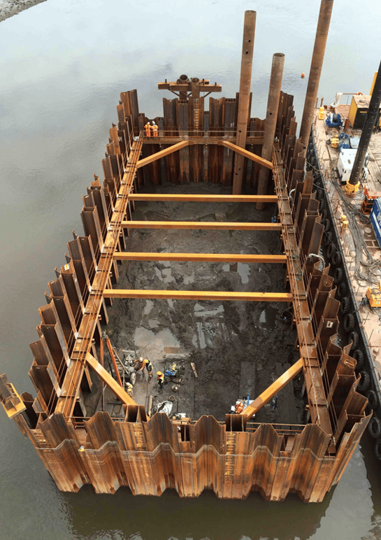 Figure 1. Submerged cofferdam using combined sections
(Source : downloaded online)
The top of the cofferdam has to be designed to a height so that it is 1 m or so higher than the highest mean sea level or the highest recorded water level in reservoir. The water level is practically constant acting on outer face of the cofferdam and the water level is gradually lowered down during the whole course of construction within the cofferdam. Normally, water pumping is followed by a minor soil excavation to the formation level in the cofferdam. The water level within the cofferdam will be risen once the construction of the structures in the cofferdam is completed. Water tightness plays an important role for the work-ability of the cofferdam.
This article examines the ability of midas GTS NX to model the sequential lowering of water table within the cofferdam until the seabed level, this is followed by dry excavation within the cofferdam and sequential rising of water table during the construction of structures within the cofferdam.
Click here to see the author's on-demand video 👇
Modelling water pressure on a retaining wall (that retaining soil) can be made easy by toggling a function called “Automatically Consider Water Pressure” in midas GTS NX, see Figure 2.
 Figure 2. Analysis Control - [Automatically Consider Water Pressure]
However, the water pressure will only be exerted on a beam element (wall) that is connected to a 2D or 3D element. In other words, the water pressure will have to be explicitly defined on the inner face and outer face of a submerged cofferdam, see Figure 3. Water pressure exerted on seabed is automatically considered once the “Automatically Consider Water Pressure” is toggled.
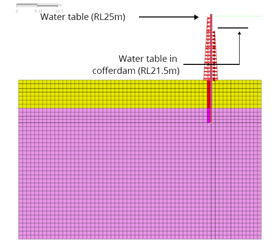 Figure 3. Water pressure is explicitly applied onto inner and external cofferdam wall
The pore water pressure in the soil is modeled by carrying out transient seepage analysis. To do this, total head was specified at the seabed level. This is to avoid the abrupt change of pore water pressure in the soil if “Water Pressure” function were to be used. Below is an example of finite element analysis of a submerged sheet pile cofferdam using midas GTS NX. The water level is at RL25 m. The seabed level is at RL 9.6 m. The final excavation level within the cofferdam is at RL 7.5 m. The cofferdam was conceived to facilitate the construction of a pump station within a reservoir. The water within the cofferdam will be pumped out until the final excavation level.
The cofferdam is designed to retain the difference of water pressure outside and inside of the cofferdam. There are 5 levels of struts within the cofferdam. Figure 4-a illustrates the 2-dimensional finite element mesh when it is dewatered and excavated to final excavation level in the cofferdam. Figure 4-b illustrates the finite element mesh at the end of construction. Typical boundary condition with roller boundary at far end was applied onto the model. Water cut-off of the sheet pile was modeled by defining lower permeability for the adjoining soil elements.
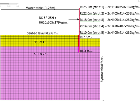 Figure 4-a. 2D FE mesh when excavate to final excavation level in cofferdam
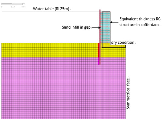 Figure 4-b. 2D FE mesh at the end of construction
The detailed construction stages adopted in the analysis are listed below;
- Initial ground water at RL25m
- Initial ground stress
- Install sheet pile wall (NS-SP-25H + H610x305x179 kg/m) and strut 1 at RL25.5 m
- Water drawdown in cofferdam from RL25 m to RL21.5 m (transient analysis, t = 3 months)
- Stress analysis
- Install strut 2 at RL22 m
- Water drawdown in cofferdam from RL21.5 m to RL17.5 m (transient analysis, t = 3 months)
- Stress analysis
- Install strut 3 at RL18 m
- Water drawdown in cofferdam from RL17.5 m to RL13.5 m (transient analysis, t = 3 months)
- Stress analysis
- Install strut 4 at RL14 m
- Water drawdown in cofferdam from RL13.5 m to RL9.5 m (transient analysis, t = 3 months)
- Stress analysis
- Install strut 5 at RL10 m
- Water drawdown in cofferdam from RL9.5 m to RL7.5 m (transient analysis, t = 3 months)
- Excavate from RL9.6 m to RL7.5m in cofferdam
- Raise water in cofferdam from RL7.5m to RL9.6m (transient analysis, t = 3 months)
- Construct RC structure in cofferdam from RL7.5m to RL9.6m (pwp in step 18 will take effect in step 19). Fill in the gap in between sheet pile wall and RC structure
- Remove strut 5
- Raise water in cofferdam from RL9.6m to RL13.5m (transient analysis, t = 3 months)
- Construct RC structure in cofferdam from RL9.6m to RL13.5m Fill in the gap in between sheet pile wall and RC structure
- Remove strut 4
- Raise water in cofferdam from RL13.5m to RL17.5m (transient analysis, t = 3 months)
- Construct RC structure in cofferdam from RL13.5m to RL17.5m Fill in the gap in between sheet pile wall and RC structure
- Remove strut 3
- Raise water in cofferdam from RL17.5m to RL21.5m (transient analysis, t = 3 months)
- Construct RC structure in cofferdam from RL17.5m to RL21.5m Fill in the gap in between sheet pile wall and RC structure
- Remove strut 2
- Raise water in cofferdam from RL21.5m to RL25m (transient analysis, t = 3 months)
- Construct RC structure in cofferdam from RL21.5m to RL25m Fill in the gap in between sheet pile wall and RC structure
- Remove strut 1
The soils were modeled with Hardening soil model and the input parameters were given in Table 1. The bending and axial rigidity of the combined sheet pile were calculated to be 1.46e7 kN.m2/m and 1.52e8 kN.m2/m. The concrete has Young’s modulus of 26 GPa and permeability of 1e-15 m/s.
 Table 1. Input parameters for soil element
Figure 5 illustrates the pore water pressure for Stage 1, 16, 21 and 30. Figure 6 illustrates the lateral movement of the soil and combined sheet pile. Figure 7 illustrates the deflection and moment in the combined sheet pile plotted against RL. The maximum forces in the combined sheet pile are within the allowable P-M curve as shown in Figure 8. Figure 9 illustrates the variation of axial load in struts over the construction stages.
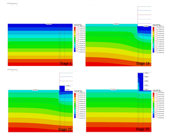 Figure 5. Modeled pore water pressure in soils for different stages
Conclusion
This article demonstrates the successful use of midas GTS NX in modelling the submerged cofferdam. It was demonstrated that the water pressure would have to be defined explicitly onto the structural element that has no adjoining soil element. Modelling excavation in submerged condition in midas GTS NX can be made easy by activating the built-in function.
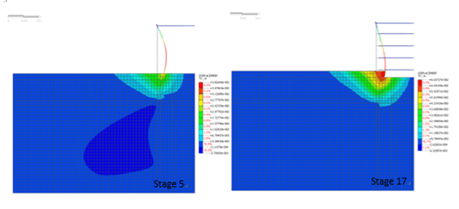 Figure 6. Lateral deflection of combined sheet pile wall at Stage 5 and Stage 17
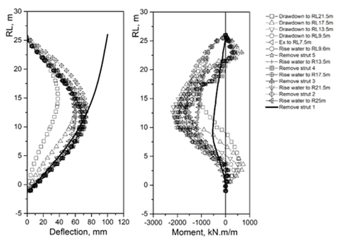 Figure 7. Lateral deflection and moment of combined sheet pile wall for all stages
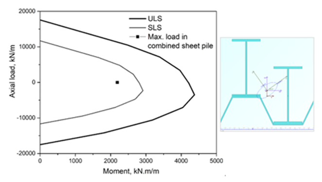 Figure 8. Compare maximum load against combined sheet pile P-M curve
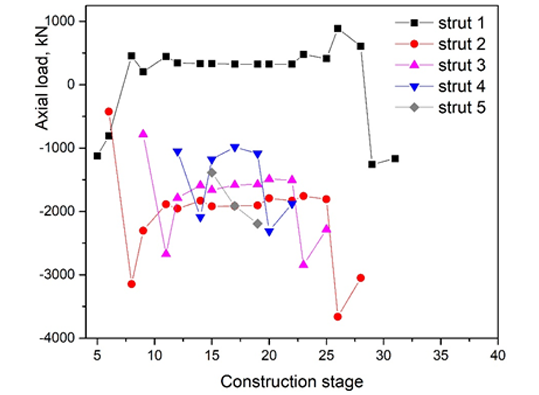 Figure 9. Axial load in struts
![[1396]how-to-model-piles-in-midas-gtsnx](https://www.midasgeotech.com/hs-fs/hubfs/geo_files/Email/20210323_CaseStudyWebinar/%5B1396%5Dhow-to-model-piles-in-midas-gtsnx.jpg?width=1280&name=%5B1396%5Dhow-to-model-piles-in-midas-gtsnx.jpg)
