Construction stage in geotechnical engineering
👇 Watch the popular case study webinar
How to quickly master the geotechnical design report
Most numerical analysis for ground over the entire construction process is done through construction stage analysis. The ground analysis is normally material non-linear analysis and the material non-linear properties can be obtained from the initial conditions within the ground. Here, the initial conditions are the in-situ conditions of the site before construction.
The general geotechnical analysis uses the in-situ stress of the ground state as the initial values. The analysis software considers the calculation of in-situ stresses from self-weight analysis to be the base. Here, self-weight analysis is the static analysis that only considers the self-weight as the external force when appropriate ground boundary conditions are applied. For consolidation analysis, the drained condition is added such that excessive pore pressure does not occur.
1. K0 method
A method that modifies the stress calculated from self-weight analysis to satisfy the K0 condition is
provided. The K0 condition for the stress components can be expressed using vertical stress σv and
horizontal stress σh as follows:
K0 = σh / σv
The K0 method uses the vertical stress calculated from self-weight analysis to calculate the horizontal
stress. The modified stress field generally does not maintain the equilibrium state with the self-weight.
If the stress is adjusted when the equilibrium state is not maintained, the stress in the continued stress
analysis continuously changes to be in equilibrium with the external force, even when there is no
change in external force, hence generating a deformation. Therefore, the K0 method is applicable
when this additional stress change is relatively small.
The general usable conditions for stress modification using the K0 method are as follows:
► When the ground shape change in the horizontal direction is insignificant
► When the pore pressure distribution does not change in the horizontal direction
► When the horizontal stress is generated by the horizontal free edge/surface boundary condition
► When the material axis is perpendicular or identical to the horizontal axis when a transversely isotropic material is used
And precautions need to be taken when applying K0 to other cases.
In particular, if the ground surface is not horizontal (sloped), the obtained stress state is not in equilibrium with the self-weight. Hence, when using the K0 method to calculate the in-situ stress for these cases, analysis needs to be performed using the unbalanced internal forces between the self-weight and calculated stress state to create equilibrium. This stage can be performed by introducing a NULL Stage, where no conditions change.
2. Self-weight analysis method
When the ground surface is horizontal, this method is equal to the K0 method where K0 = ν/(1-ν). If not, a horizontal strain exists and a different result from the K0 method is deduced along with shear stress. Hence, it is generally recommended that the self-weight analysis method be used for sloped ground. However, it is impossible to use a K0 value larger than 1 and the K0 method needs to be used when using a large K0 value.
After the initial stresses have been obtained from the initial conditions, the excavation loading and Shear strength from applying material properties can also be obtained. Hence, construction stage analysis includes the sequential construction process, starting from the initial ground conditions. Because on-site construction stages are very complex and subject to change, the analysis simplifies the process and focuses on the important construction stages.
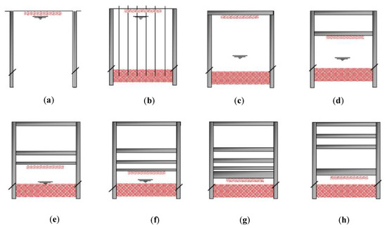
For example, the construction stages for a tunnel are as follows.
1 Stage: Initial ground stress
2 Stage: 1st face excavation
3 Stage: 1st reinforcement + 2nd face excavation
4 Stage: 2nd reinforcement + 3rd face excavation
5 Stage: 3rd reinforcement + 4th face excavation ……
(Repeat) ……
GTS NX has a special wizard to efficiently define the construction stages. A regular number (postfix) needs to be assigned to each set to define the construction stage using the wizard. This number can be assigned using the [Rename] function for mesh sets. Sets that are only used once in the entire construction stage process don't need to be assigned a number.
GTS NX does not create an independent analysis model for each construction stage. Rather, it uses a cumulative model concept where only the structural or loading changes are input for each construction stage and the analysis results are accumulated from the previous stage analysis results. Therefore in the construction stage analysis, the structural changes and loading history from the previous stage affect the next stage analysis results.
The definition of the construction stage is done by dragging & dropping the mesh set, boundary setting, load set, and contact set into the activated data column or deactivated data column.
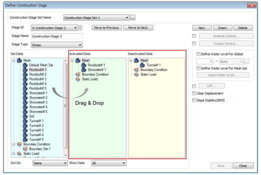
Define Construction Stage
The video below shows the easiest way to automatically generate the construction stage. Auto Set enables to automatically register the displayed meshes, boundary conditions, load conditions on the activated data column and the un-displayed meshes, boundary conditions, load conditions on the deactivated data column.
👇 Watch the popular case study webinar
[GTS NX] Auto-Construction Stage Feature