🖱️ Click to jump
2. Preparation of 3D FEM-based numerical model
1) Geology and spatial location of rock layers
2) Material properties and strength hypotheses
Introduction
The room-and pillar system is one of the oldest methods of underground mining of a deposit located in hard rocks. In general room-and-pillar method is a mining system in which the mined material is extracted across a horizontal plane, creating horizontal arrays of rooms and pillars. The whole process of exploitation is based on "rooms" created after the ore is dug out, and "pillars" which are unexcavated material left to support the roof stratum.
Unfortunately, the determination of the size, shape, and spatial location of pillars is a very complex procedure and still is the topic of numerous research activities (Hudeček, 2017). This method of ore exploitation is used for the excavation of horizontal deposits. According to past experiences, room-and-pillar mining is very advantageous because it can be mechanized, and is relatively simple.
As it was pointed out by (Croyle et al., 1987) room-and-pillar mining was one of the earliest methods used. Initially, the exploitation was carried out in a non-systematic manner, i.e. the size of the pillars was selected empirically, and the access ramps and sidewalks were led in the most convenient directions. The first experiences of mining with the use of the room-and-pillar system lead to the conclusion that the chaotic manner of cutting the deposit negatively affected the ventilation conditions (Figure 1).
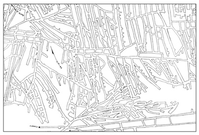 Figure 1_ Room and pillar mining at The Georges Creek Big Vein mine (Young, 1917)
Moreover, numerous rock bursts and roof falls occurred frequently, which was related to the inappropriate selection of the geometry of the technological pillars. In hard coal mines, pillars of too small dimensions were often compressed and crushed by the overlying roof layers, thus adjacent pillars took the greater part of the load.
As a result, a specific chain reaction occurred, which was very difficult to control, and most often destroyed a significant part of the mine (Andros, 1915).
Based on the experience gained, steps were taken to standardize the technological parameters of the room and pillar system to adapt it to the specific conditions of the deposit. The mining scheme began to be planned in a way that allowed for a compromise between safety and production rates.
Underground copper mines in Poland may be a good example of planning and adjusting room-and-pillar mining systems to different geologic conditions.

Image 1_ Rudna mine in Poland (Image source: KGHM website)
So far, over 45 varieties of room-pillar systems have been developed in Polish copper ore mines (Butra and Kicki, 2003). Each variant was explicitly adjusted to local conditions by changing room and pillar size, heigh of the workings, direction of exploitation, and the opening size (the distance between the exploitation front and goafs). All these parameters affect both the ventilation conditions and the time when the roof layers will deflect/collapse. The greater the distance, the softer the process of roof deflection. The opening size is defined as the line in which the technological pillars need to be reduced to post-destructive dimensions, which allows them to go into a more yielding state (Figure 2).
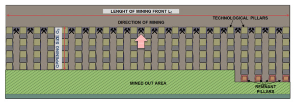 Figure 2_ The basic diagram of the room-pillar system
Currently, 22 variants of this system are used. Description and detailed conditions for the use of individual systems are presented, among others in catalogs of mining systems for KGHM mines (Cieślik et al., 1991; Dębkowski et al., 2001; System catalog, 2010). The evolution of room-pillar mining systems in Polish copper ore mines is shown in Figure 3.
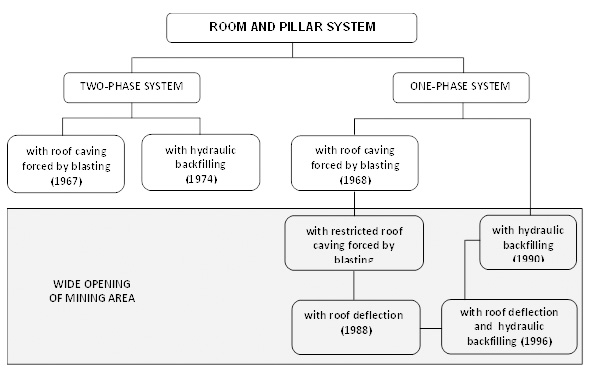 Figure 3_ Evolution of mining systems in Polish copper ore mines
Of course, appropriate planning of mining works in relation to local geological conditions gives tangible benefits in the form of minimizing the geomechanical hazard and increasing the efficacy of mining works. According to recent experiences mining method, scheme of deposit excavation roof control method, and concentration of mining activities affect most visibly current seismic and rockburst hazard in Polish copper mines (Figure 4)
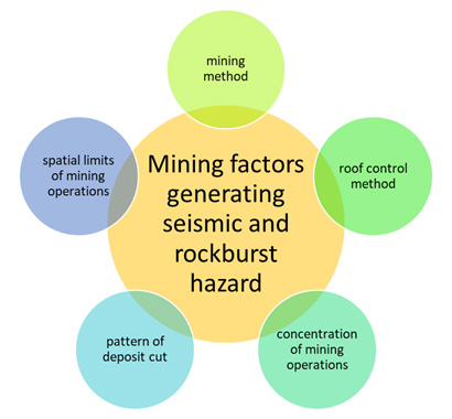 Figure 4_ Mining factors generating seismic and rockburst hazard
A confirmation of these words can be, Figure 5 which shows the distribution of seismic activity in KGHM's mines over the last 30 years. As you can see, modifications to the methods of selecting a deposit translated into a clear decrease in seismic activity recorded in the following years.
.jpg?width=602&name=Figure%205_%20Seismic%20activity%20in%20LGCD%20(SW%20Poland).jpg) Figure 5_Seismic activity in LGCD (SW Poland)
Figure 5_Seismic activity in LGCD (SW Poland)
Nevertheless, it has to be pointed out that despite the clear effectiveness of the actions taken, based on simple analytical calculations and the experience of the mine staff, the process of minimizing the seismic hazard by modifying the methods of selecting was extended over several years which, from the point of view of economic results and accident rates, was a very unfavourable situation.
Moreover, when analysing figure 5 it may be observed that the level of activity has stabilized since 2008, but remains high. This could mean two things:
- the methods we are currently using are already optimal and there is no way to further minimize seismic activity.
- the possibilities of methods based strictly on the experience of mine management have already run out and it is necessary to implement new, more advanced calculation methods for regular use.
And these issues led to the moment where it is worth considering if the implementation of numerical modelling the regular use in the planning of underground excavation could bring benefits to the sustainability of the whole mining process.
At the moment, even though modelling tools have been available for many years, in mining practice they are not used regularly for the design of mining works. Analyses, e.g. using the finite element method, are used rather in certain special cases, e.g. to analyse the causes of very serious accidents or to analyse the geomechanical risk in areas characteristic of the key infrastructure or the occurrence of specific deposit conditions, such as all kinds of faults
Within this article, the case study of numerical modelling of underground excavation with GTS NX software has been presented. The analysis has been performed within the Baltic Sea Underground Innovation Network project and was aimed at the evaluation of the stability of the conceptual trial mining panel, which potentially could be set up in the Polkowice-Sieroszowice copper mine.
👇 Case Study | FEM Analysis for Underground Mine Stability
Preparation of 3D FEM-based numerical model
In the first stage, it was necessary to prepare a site plan for the excavations and design a place where is planned place underground laboratory. The general assumption was that the laboratory, for technical reasons, should be located approximately 1,200 meters from the nearby SW1 ventilation shaft. It is one of the main ventilation shafts of the Polkowice-Sieroszowice mine.
The description of the underground site is as follows (figure 6):
- The workings that have already been excavated, but not yet closed, are marked in blue. This means they are still available for transport, ventilation, etc.
- The backfilling areas are marked in green. As you can see, in the vicinity of the shaft, some of the mining fields were backfilled with the use of hydraulic and dry backfilling to increase geomechanical safety. And the brown area represents the intact rock mass.
- the underground laboratory project was marked pink in colour.
Generally, the total length of all workings planned to be excavated for the construction of the laboratory is about 9 km.
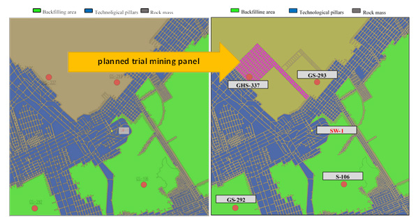 Figure 6_ Projected excavations of the underground laboratory
The planned experimental mining panel will provide access to 4,300 meters of mining excavations intended for research purposes. In addition, in the first phase of the project, it will be necessary to build an additional 4,500 m of preparatory workings, within which transport and evacuation routes will be located.
Of course, since the designed mining panel was not a standard exploitation field, it was necessary to take into account the necessity to maintain the designed excavations for a longer period, reaching a few or even several years. Therefore, the designed dimensions of the pillars were much larger than the standard pillars used within the mining fields. The designed width of the pillars was about 15 m, while their length was 30 m (Figure 7).
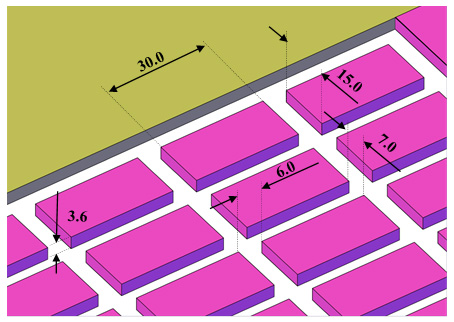 Figure 7_ Dimensions of rooms and pillars within developed mining panel
Additionally, within the designed operating field, 8 special-purpose chambers were designed, e.g. machinery chambers, chambers for scientific equipment and materials storage, or mining chambers, where the crew can stay in the period between shifts. These 8 chambers had larger dimensions and therefore single chamber was 6-10 meters in width, 15-20 meters long, and 6-9 meters high (Figure 8).
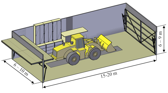 Figure 8_ Dimensions of functional mining chambers
1) Geology and spatial location of rock layers
When the geometry of the excavations located at the deposit level was ready, it was necessary to prepare the geological model of the layers located above and below the planned mining panel. For this purpose, the bedding plane tool available in the GTS NX software was used. This tool allows for the mapping of the real geologic system of layers based on data from exploration drill holes in a very simple and quick way. In the case of the developed model, data from four boreholes were used (Figure 9).
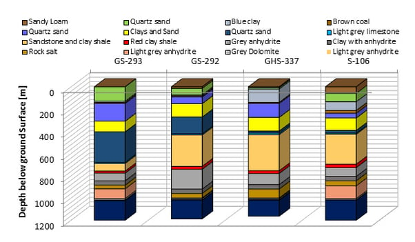 Figure 9_ Stratigraphic profiles within the surrounding of the analyzed area
It has to be highlighted that the bedding plane tool, although very easy to use, greatly facilitates the modelling process and increases the accuracy of the simulation. Of course, accuracy increases as the number of boreholes but in the case of the above mentioned analysis 4 were enough.
It has to be emphasized as well that the prepared numerical model was characterized by very large dimensions. The cuboid presented in figure 10 has dimensions in the x and y directions at the level of 2x2 km, while the Z component is 1.5 km. Still, the use of the GTS NX software guarantees the possibility of stable calculations of such large-size models.
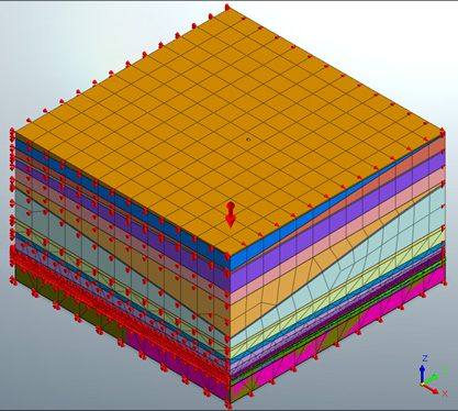 Figure 10_ Dimensions of developed numerical model
2) Material properties and strength hypotheses
The next stage of our numerical modelling is the selection of appropriate rock strength parameters. The question here always arises whether to use data from laboratory tests or try to reduce the strength of rocks based on various analytical formulations? In general, this problem is very complex and complicates the entire modelling process, but some assumptions must be made.
In the case of geomechanical analyses, it is better to slightly underestimate the strength parameters of rocks than to overestimate them. Therefore, when preparing data for numerical models, the so-called rock mass classifications may be used. There are several types of rock mass classifications, with the Hoek GSI classification being the most popular and possibly the most accurate. The description of GSI values concerning observed/predicted rock mass disintegration was presented in figure 11.
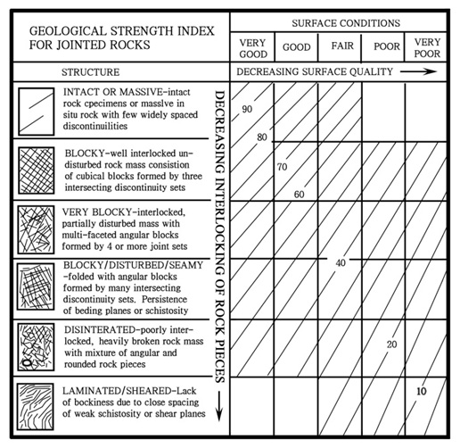 Figure 11_ GSI scale
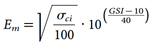
This method is based on a qualitative assessment and now, depending on the degree of fracture of the material, the appropriate GSI level is selected, which is then used to calculate/reduce the parameters describing the strength of the rocks. For example, it is possible to reduce the deformation modulus, in accordance with the relationship shown below, by using the GSI value and the value of uniaxial compressive strength resulting from laboratory tests.
This approach is very simplified, but it is well suited to the FEM calculations. Of course, the GTS NX program allows to simulate of cracks within the model, but with the geometry at the level of several cubic kilometers, introducing the crack network to the numerical model would significantly extend the calculation process and would involve the need to engage much more powerful hardware resources.
As a result, in the case of an intact, non-cracked rock mass, the GSI value was assumed at the level of 80 points, in the zones directly surrounding the excavation and in the technological pillars, the GSI value was at the level of 40-60, while in the case of liquidation zones, the GSI scale was not used, and these areas were filled with loose material (Sands and gravels). Therefore safety factor of these zones should be equal to 0, but still, it generates some kind of support for above-located roof layers (Figure 12).
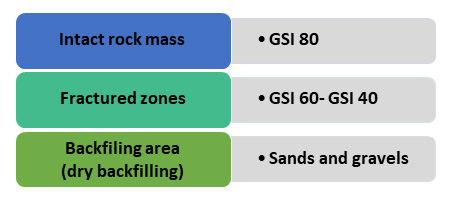 Figure 12_ The determination of material properties for undisturbed rock mass, excavations, and backfilling areas
Another element is the selection of an appropriate strength hypothesis. In the analysed case, an elastic-plastic model using the Mohr-Coulomb strength hypothesis was applied.
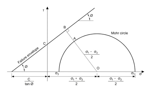 Figure 13_ Mohr-Coulomb Failure Envelope
Generally speaking, in a static load system, this strength criterion allows for a good reflection of the actual situation in the rock mass, which was verified many times based on in-situ tests.
Analysis in MIDAS GTS NX software also allows for determining changes in stresses, strains, displacements, and safety factors. To provide the results of the analysis in understandable form even to customers who do not specialize in rock mechanics, the condition of the rock mass was presented using the so-called safety factor (SF).
If the principal stresses are known at a specific location, the factor of safety at that location can be calculated using the following formula:
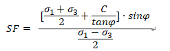
Where,  and
and  main stresses,
  cohesion, and
  angle of internal friction .
Safety factor values less than 1 indicate areas prone to instability.
👇 Case Study | Numerical Analysis of Tunnels in Anisotropic Rock Mass Formations
3) Mesh
And last but not least, one of the key elements of the entire process of preparing the numerical model, i.e. the preparation of the mesh. For practical reasons, it is not justified to use the same size of the mesh for the entire model, because such an approach would involve the generation of several billion finite elements. In such a case it is necessary to increase the size of the elements while keeping in mind the necessity to use the mesh dense enough to make the calculation results reliable.
On basis of trial simulations, the optimal size of the mesh at the level of mining panels has been determined. According to performed calculations, it is optimal to use elements with a size of about 1 m within the mining area (Figure 14).
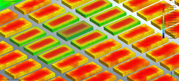 Figure 14_ Comparison of safety factor distribution in dependence of different mesh size
Above calculated values of the safety factor for pillars made of elements with a size of 0.25 meters, 1 meter, and 3.5 meters. One may observe that the differences between 0.25 and 1 meters are almost invisible while increasing the size of the elements to 3.5 m significantly deteriorates the results.
What is worth mentioning is the fact that the GTS NX software has a very efficient and accurate mesh generator, thanks to which it is possible to prepare the first version of the mesh in automatic mode, and then the model may be manually checked and cleaned of elements with incorrect angles or dimensions. Additionally, a useful function of the GTS NX program is the possibility of using a hybrid mesh.
Due to the stability of calculations, triangular meshes at the deposit level may be used, which is related to the high complexity of the workings (Figure 15).
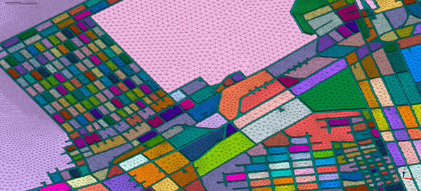 Figure 15_ The meshing of deposit level
Then, moving away from the designed workings level, it is possible to increase the size of the elements and switch to the hybrid mesh mode, which significantly reduces the number of model elements. As you can see on this slide, in extreme cases the size of an element increases from several dozen centimetres - within deposit level, to about 100 meters - on the ground Surface (Figure 16).
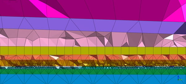 Figure 16_ Using hybrid mesh to increase element size and reduce the number of elements with increasing distance from the analysed mining panel
4) Results
Finally, the model prepared as part of the Baltic Sea Underground Innovation Network project included about 4.7 million finite elements, so it was a relatively large model, but the GTS NX program does not have any problems with calculations of models of such sizes as long as the mesh and model are well prepared and cleaned of any elements that could badly affect the stability of the solution.
One of the parameters which have to be analyzed is shear stress distribution. As mining practice shows, especially in recent years, shear stresses may appear in some areas of the mine and are particularly harmful because both the strength of the rocks and the strength of the rock bolt support used in KGHM mines are relatively low in the case of shear strength compared to axial strength.
At the moment there is no available roof support system that would enable effective protection against these stresses. Rather, technological measures should be used in this regard. So, for example, knowing that in some areas of mine high values of shear stresses are observed it will be possible can choose a different geometry of excavations, or select a different direction of exploitation. Nevertheless, for technical reasons related to the operating systems used, high values of shear stresses may appear in some areas of our model. The location of these areas allows us to take appropriate preventive measures to relieve these stresses, or in extreme cases, you can exclude selected workings from use.
The distribution of shear stresses in the surrounding of the analyzed mining panel is presented in figure 17.
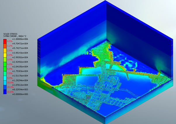 Figure 17_ Distribution of shear stresses
Another parameter that can be analyzed based on the results of numerical modelling is the location of areas where pillars may be pressed into the floor layers. In the case of the copper ore deposit in the area of LGCB, the floor layers are mainly composed of sandstone layers, which are relatively soft compared to the carbonate layers lying on the roof of the deposit.
Now, when analyzing the distribution of the Safety Factor within the floor layers in the vicinity of workings, it may be observed in which areas of the model pillars tends to be pressed into the floor layers. Generally, in this model, within the analyzed excavations, there are no significant areas where the pillars will actually be pressed into the floor. Of course, near the goaf, there is an area of concentration of low Safety Factor values, and on the contours of the projected mining panel, however, this is not a level that indicates a potential threat which is generally consistent with observations performed under in-situ conditions (Figure 18).
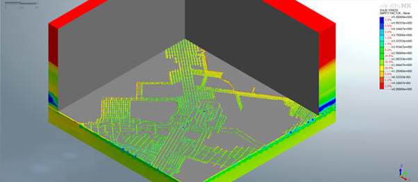 Figure 18_ Distribution of safety factors within the immediate floor of underground workings in the analysed area
Knowing that the floor layers should withstand the pressure of the pillars with the designed geometry, the stability analysis of the pillars within the analyzed area may be performed. In the case of the projected mining panel intended for R&D purposes, Safety Factor values were at a high level exceeding the value of 2, and any areas of instability were not observed. However, it is worth paying attention to the pillars located between the two areas of backfilling. As can be seen in the backfill areas, the Safety factor reaches the value of 0, which proves that this area is completely yielded (Figure 19). On the other hand, some of the technological pillars between the backfilling areas are characterized by safety factors lower than 1, which indicates the probability of failure. With this knowledge, you can take preventive measures, such as installing additional hydraulic roof support at intersections or designing pillars with larger geometry at the stage of projecting underground excavation.
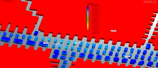 Figure 19_Distribution of Safety Factor within pillars located between areas of backfilling.
In figure 20, the values of the safety factor calculated for the roof layers are presented. Exactly 25 centimetres above the mining level. As you can see, the roof above the existing workings and the projected mining panel is characterized by high values of the safety factor, most often exceeding the level of 1.25. The areas of instability occur only above the backfilling area, while regions with very high SF values can be observed above the area the intact rock mass, which is consistent with the underground observations.
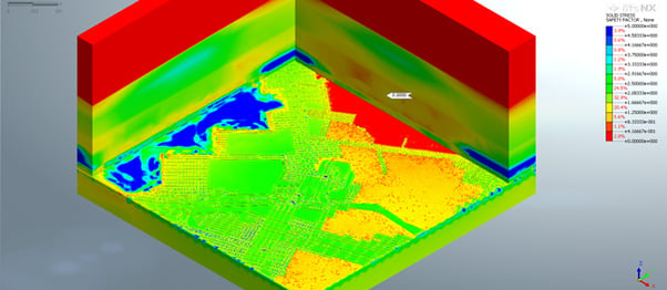 Figure 20_Stability of roof layers in surrounding of analysed area
Conclusion
The use of three-dimensional numerical modelling in a static load system using the finite element method significantly affects the possibility of supporting the design of underground mining and increasing the accuracy of geotechnical analyzes and risk assessments.
Determination of parameters such as the safety factor, stress distribution, pressure zone range, as well as the location of the overloaded zones, is the basis for rational planning of the geometry of excavations, selection of the rock bolt support type, or designing destress blasting works, which are the basic elements of rock burst prevention in the LGCB region.
The use of the GTS NX software for modelling the above-mentioned conditions enables the preparation of large-size models with dimensions of several cubic kilometres, which is crucial from the point of view of geomechanics and stability analyzes of workings in room-and-pillar mining systems.
👇 Case Study | FEM Analysis for Underground Mine Stability

⭐ Recommendation (Click)
- Blog | Numerical Analysis of Tunnels in Anisotropic Formations - Continuum and Discontinuum Approaches
- Blog | Design Tips For Retaining Walls In Excavation Works
- Blog | The Advantages Of 3D Analysis In Major Fields
Reference
-
Hudeček V., Šancer J., Zubíček V., Golasowski, J. (2017), Experience in the Adoption of Room & Pillar Mining Method in the Company OKD, a.s., Czech Republic. Journal of Mining Science. 53 (1): 99–108. doi:10.1134/s1062739117011908. hdl:10084/124488.
-
Croyle, F.D., Kohler J.L., Bise C.J. (1987), Maximum Demand and Demand Factors in Underground Coal Mining. IEEE Transactions on Industry Applications. IA-23 (6): 1105–1111.
-
Pedrazzini A., Jaboyedoff M., Froese C. R., Langenberg C. W., Moreno F. (2011). Structural analysis of Turtle Mountain: origin and influence of fractures in the development of rock slope failures. Geological Society, London, Special Publications, 351(1), 163–183. https://doi.org/10.1144/SP351.9
-
Young C. M., (1917), Percentage of Extraction on of Bituminous Coal with Special Reference to Illinois Conditions, Engineering Experiment Station Bulletin No. 100, University of Illinois, page 130
-
Andros S. O., (1915), Coal Mining in Illinois, Illinois Coal Mining Investigations, Bulletin 13, Vol II, No. 1, University of Illinois.
-
Butra, J. and Kicki, J. (2003). Ewolucja technologii eksploatacji złóż rud miedzi w polskich kopalniach. [The evolution of copper ore deposits mining technology in Polish mines.]pracazbiorowa pod red. Jana Butry i Jerzego Kickiego; Instytut Gospodarki Surowcami Mineralnymi i Energią Polskiej Akademii Nauk: Kraków.
-
Cieślik, Z., Iglewska, J. and Janowski, A. (1991). Katalog Systemów eksploatacji dla kopalń KGHM, KGHM Polska Miedź S.A., Lubin
-
Dębkowski, R., and Parchanowicz, J. (2001). Katalog systemów eksploatacji dla kopalń KGHM. CBPM ‘Cuprum’: Wrocław.
-
System catalog KGHM Polska Miedź S.A. (2010). Katalog systemów eksploatacji złóż rud miedzi dla kopalń KGHM Polska Miedź S.A., KGHM Polska Miedź S.A., Lubin.