Analysis of a Deep Excavation in Diaphragm Walls, on Surrounding Buildings
🖱️ Jump to the contents (Click)
1. Introduction to Diaphragm Walls
2. Construction of Cast In-Situ Diaphragm Walls
3. Case Study Analysis4. Design Project5. Results6. Analysis of Surrounding Objects7. Summary and Conclusions
8. Bibliography
Introduction to Diaphragm Walls
1. History of Diaphragm Walls
The technology of the diaphragm walls starts over half of century ago when in 1948 this technology was first tested. In the 1950s this method of excavation support was used during the Milan Metro construction by the Impresa Costruzioni Opere Specializzate Company.
The new tunneling method was first known as the Milan Method and soon found use in other types of constructions. The technology was introduced to the rest of the EU countries and finally to the United States, wherein in 1962 this technology was first applied. It was rising in popularity and following objects such as the Bank of California in San Francisco, the CNA Building in Chicago and the World Trade Center in New York took benefit from it, among many others [1].
2. Overall Description of Diaphragm Walls
A diaphragm wall is concrete structure made within the deep excavation trench, cast on site (in -situ) or using precast panels. The ability of application in nearly every soil condition, technology allows creating walls to depths of 100 meters down the ground and to widths varying from 0.45 to 1.5 meters. A valid advantage of the technology is that the execution of the structure makes very little vibration and noise.
Effects of vibration in urban areas can cause great damage on surrounding buildings, thus they are especially suitable for civil engineering designs in spaces that are densely-populated.
Low deformations made by machines and low permeability of water makes diaphragm walls advisable technology to retain excavation pits in the direct vicinity of existing constructions. The closeness of existing structures to the excavation and presence of groundwater makes them often both most technically and financially favorable solution. Diaphragm walls can be used as temporary support or fully load-bearing element of the building and combined with or without anchorage systems. In load bearing layers of soil they are also used as foundation, collecting concentrated loads from upper parts of building. This technology is called “Barrette” [1], [3], [5].
Construction of Cast In-Situ Diaphragm Walls
1. Guide Walls
At the beginning of constructing a diaphragm wall preparation work needs to be done. First, the geodetic survey is needed, second – the stable working platform needs to be performed for heavy equipment. Platform should be at least 1,50m above the level of groundwater.
Usually, cast in-situ walls construction begins with guide walls Construction begins with guide walls, which are parallel temporary walls, mostly made of precast concrete. First, the trench needs to be excavated to 1-2 meters, then two guide walls are placed there. Depth of the excavation to place guide walls can be deeper. Mentioned 1-2 meters are commonly used by engineers, however guide walls need to be constructed on bearing substrate. Distance between the guide walls is the same, as designed finished diaphragm walls, with clearance taken into consideration – 25 to 50 mm.
In general, it is a continuous reinforced concrete beam, which provides stability in the fragile part of the trench – the upper part. It also supports temporarily the reinforcement cages. Moreover, it defines designed path of diaphragm walls on site. This is very important step, a sketch of future success in creating diaphragm wall [3], [4], [5].
2. Excavation
Next step is execution of the excavation. Dimensions of the excavation are connected with the equipment used. Most commonly used width varies from 50 to 100 cm, and its length is usually no longer than 6 meters. As the excavation proceeds, there is supporting suspension brought inside. Slurry prevents the excavation from collapsing. Many types of machines are used to deepen the excavation, but most common are the drilling grabs.
This jaw-like bucket provides high efficiency in deepening trenches. Streamlined shape overcomes resistance of slurry during execution. Machines using grabs are cable or hydraulic operated. Important technologic issue is to deepen the jaws slowly to avoid waves of the slurry, which could damage the wall. After the grab is brought to the bottom of the excavation, soil is loaded and taken out by lifting the grab to the surface. Kelly type of installation provides excavation up to 35 meters deep, although cable-suspended drilling grabs can drill even deeper, due to technologic factor of height of the Kelly rod.
The length of the panel is associated with opening jaws, and commonly varies between 220 and 280 cm. As the excavation is proceeding, supporting fluid (usually bentonite) is pumped to support the trench from collapsing. The level of the slurry should be lower than height of guide walls, but also higher than highest piezometric surface. During the excavations, weather conditions vary, so the level of fluid should always be monitored.
As mentioned before, most common fluid used for filling excavation is bentonite clay, which after mixing with water shows viscous and thixotropic properties. It is widely used due to low cost, reliability and availability, however more supporting fluids are introduced in civil engineering. Polymer based fluids are recently being developed and researched, but complexity of preparing it in situ makes bentonite-water mix most solid solution. Standard EN 1538:2010 defines properties of suspension materials – density, viscosity, pH value, filtration and sand content. It is important to add, that thixotropic material must have greater pressure of ground and water to maintain stability of the excavation.
In certain, assumed time samples of the slurry should be taken and tested in the laboratory to determine properties mentioned above. Standard describes the measures of the slurry, which after application improve the operation of the suspension. In case of weak (soft) soils, it is recommended to increase density of the fluid. What is more, the time when the trench is open should be shortest as possible. Open trench without slurry is exposed to great danger of collapse. In this case, more bentonite should be added to fill the void. To avoid loss of the supporting fluid, there should be added material to fill the supporting fluid.
After the designed depth is reached, the supporting fluid needs to be cleaned and in the same time, replaced inside the trench. When the time of fluid presence in the trench is too long, particles fall to the bottom of the trench, and the density of the slurry begins to be different – the bottom starts to be denser. If the suspension material loses its stability, underground water can penetrate the trench and cause great damage. The bottom of the trench is usually cleaned by compressed air [3], [4], [5], [11].
3. Reinforcement
When the excavation is completed, stop-end elements are placed inside. The role of the stop-end joints is to execute tight connection between the adjacent panels. The cross-section is usually O- section (pipe) or I-section.
Directly after execution of the excavation, stop-end elements should be embedded. Stop-end joint, which role is to ensure the tightness between adjacent panels is in form of steel pipes or I-section. After the trench is cleaned and stopend joints are mounted, reinforcement should be placed. The standard EN 1538:2010 suggests not less than 20 centimeters of void between the bottom and the lowest bars of reinforcement. Spacers, made of ceramic, polystyrene and plastic, are used to maintain this distance.
Moreover, the minimum distance between the ends of the reinforcement cages within the panel should maintain at least 20 centimeters and between the panel joints and cages – 10 centimeters. The cage should be rigid enough to transport it and place it inside the trench without damage. After the reinforcement is mounted inside the trench, final part is concreting [3], [4], [5].
4. Concreting
Concrete is piped by one or more pipes, depending on the largeness of the project. Most commonly used are tremie pipes with hopper at the top. The diameter of the pipes should be at least 15 centimeters and 6 times bigger than the greatest aggregate size (if not, the aggregate could block the pipe). The outer diameter should fit in between the reinforcement bars without interruption.
The concrete is piped continuously and uniformly from the bottom to the top of the trench. It is highly undesirable for concrete and supporting fluid to mix, and thus the filler pipe has an enclosure of concrete cap. After the pipe is at the bottom of the trench, the cap is removed and pipe is slowly taken higher by approximately 10 centimeters to allow the discharge of the concrete mix. As the concrete and slurry should not mix, the speed of lifting the pipes should not be too fast; it is suggested not to be more than 3 meters per hour.
Moreover, the pipes should be moved and rotated in horizontal direction, because the concrete spreads better and it prevents adhesion of concrete parts to the pipe. Standard EN 1538:2010 also refers to number of pipes per meters, which in normal circumstances, should be one per 2,5 meters of length, or per one reinforcement cage. What is important to add, concrete should be poured simultaneously from all pipes.
Concreting should be carried out without any interruptions, thus vibrators cannot be used. Bentonite suspension should be able to reuse, after cleaning. At the end, the cut-off level should be filled with additional layer of concrete to maintain designed quality of the panel. Consistency and composition of the concrete should reach designed requirements. Pumped concrete should be liquid correspond to a slump value of 180-210 mm. Amount of cement in concrete mix is derived by maximum aggregate size and picked to match the strength requirements. Cement to water ration should be lower than 0.6.
Fine fractions negatively impact the mix, so they should be minimalized. Maximum grain size, recommended by the standard is 32 mm. The top layer’s resistance is lowered, because of concrete and suspension material mixing. Trimming and leveling the surface lowers the potential damage and helps to maintain smooth surface, although the operation should be carried out carefully [3], [4], [5].
5. Joints
Diaphragm walls technology is based on alternative panels, which are connected by the joints. For obtaining best performance of diaphragm walls, the connection must be properly executed. Method of joining the panels depends on the type of machines doing excavation. In case of grab-type machine, joints are made by using steel or concrete stop -ends. In most cases, the joint is a smooth, steel tube, with diameter equal to the width of the trench, to maintain continuous, smooth surface of the wall. Placed vertically, they prevent from making gaps within adjacent panels. Joints are mounted inside the trench before concreting by crane, and removed after concreting by hydraulic pipe extractors.
When removing, it is extremely important not to hurry, because concrete can get inside the pipe. However, if the tube is too long inside, it can be nearly impossible to take it out, due to bonding to the concrete. Other option to join the panels is to use steel flat joints, with one or both sides covered in tapes, which ensure the solidness and tightness of the connection [3], [4], [5].
Case Study Analysis
1. Case Study Description
The plot is localized in highly urbanized area – city center of Poznań. Some of the most famous buildings of Poznań, are in the close distance to the plot, for example Old Brewery mall – Stary Browar. Two main streets are adjacent to the plot – Królowej Jadwigi (transit route) on the south and Kościuszki on the north. On the west and east, there are high rise buildings – Norvotel and Andersia Tower. Elevation of the ground surface differs from 65.8 to 69.5 meters over the sea level. The surface is tilted slightly towards the river Warta.
The design project concerns casing of the excavation using diaphragm walls. The area of the excavation has dimensions 50 x 70 meters. The designed excavation is 12 meters deep and is integral part of the future sky scraper and a base for the next stages of the investment – concrete slabs, the core, walls and floors, which are not included in this paper. Thickness of the diaphragm wall is constant and equals 1 meter.
The ground conditions were simplified and implemented in the Midas GTS NX software program, as well as the stages – construction of diaphragm walls and excavation within them. The considered model has 130 x 170 meters and the adjacent buildings are implemented to best visualize the real conditions. Final step is analysis of the impact of the excavation on these buildings. This analysis is also performed in the same software [3], [4], [5], [6].
2. Ground Conditions
Based on the geological structure of the ground, groups of soil were introduced. Every group differs in lithology, origin, and consistency. The base of diversification was geological survey (static and dynamic) and laboratory tests [2], [9], [10].
- Group I
Group of made ground with mix of rubble, bricks, rocks and sands varies from 2.0 to 7.5 meters deep:
IA – nN [Pd+Ps+Gb+…];
IA1 – loose qC ≤ 3,0 MPa ID ≈ 0,25;
IA2 – semi-dense ID ≈ 0,40;
IA3 – dense qC ≥ 15,0 MPa ID > 0,65;
IB – nN [G+J+Pg+…];
IB1 – plastic qC ≤ 1,0 MPa IL ≈ 0,40;
IB2 - plastic/hard-plastic qC ≥ 2,0 MPa IL ≈ 0,25.
- Group II
The second group of Pleistocene materials consists of both cohesive and noncohesive dense clays and sands. Within the group there were several layers introduced:
IIA – Clayey silt with sands Gp Gp//Pd Gp+//I
IIA2 – hard-plastic / semi-solid IL ≈ 0,05;
IIA3 – semi-solid IL ≈ 0,00;
IIA4 – semi-solid / solid qC ≈ 10,0 MPa IL < 0,00;
IIB – Fine sand Pd ;
IIB1 – dense qC ≈ 30,0 MPa ID ≈ 0,75.
- Group III
Group of Poznań clays; genetic category D, with local sand areas. Within the group there were several layers introduced:
IIIA – clay I
IIIA1 – hard-plastic IL ≈ 0,15;
IIIA2 – hard-plastic IL ≈ 0,05;
IIIA3 – semi-solid qC ≈ 2,5 MPa IL ≈ 0,00;
IIIA4 – semi-solid / solid qC ≈ 3,5 MPa IL < 0,00;
IIIB – Sands with silt Pπ;
IIIB1 – dense ID ≈ 0,75.
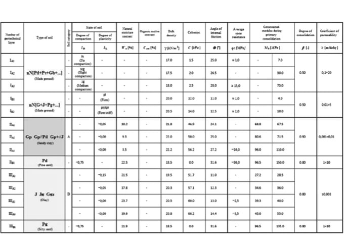 Table 1. Geotechnical Parameters of the Examined Layers
3. General Assumptions for the Design Project
Stages of Construction
In this paper, the main project concerns deep excavation in diaphragm walls and analysis of impact on surrounding buildings based on documentation and surveys of area in city center of Poznań, Poland.
The design is performed in three stages:
- Stage I, where the ground conditions are modeled in software
- Stage II, where the construction of diaphragm walls and neighbors as cantilever structures are modeled. To obtain the best results the neighbors are supported by two weightless slabs; the loading is added
- Stage III, where excavation is performed within the diaphragm walls to the clay layer, struts added.
- Stage IV, where the rest of the excavation is performed [6].
Assumptions for the Design Project
Following aspects of the investment were assumed for the design project:
- The main geometry, height levels of constructions, coordinates, area, ground conditions were obtained from soil survey and site inspection.
- Phases of construction are introduced to match the real process of work in this type of structures.
- The loading added on the surrounding buildings was assumed and uniformly distributed, representing weight of the neighboring buildings; self weight of the structures is an output of the modeled materials.
- The boundary conditions are auto generated by the software.
- Parameters of soils are result of soil survey.
- The weightless slabs are modeled to provide support to the neighboring structures. Their stability is assumed, not calculated, because they are not main subject of the design project.
- Linear analysis is performed by the software.
- The diaphragm walls and the excavation are located in the central part of the model, and the mesh is denser in the central part, and less dense in outer parts [6], [8].
Implemented Ground Conditions
The cross section, which was the base of the ground conditions implemented in the software is joined to the paper as attachment. The soil modeled in the software is simplified, but close to the existing state of ground. From the ground surface to the bottom the layers are:
- Man-made ground consisting sand, organic sand, clayey sand and bricks (68.0 – 62.00 meters above the sea level);
- Clay with sand (66.00 – 62.00 meters above the sea level);
- Fine Sand (64.00 – 60.00 meters above the sea level);
- Poznań Clays (62.00 – 68.00 meters above the sea level - bottom level of the model) [9], [11].
Design Project
1. Model of the Structural Elements
The presented structure – diaphragm walls, as well as modeled existing surroundings are created to simulate the real conditions. The model used to simulate the structure is an isotropic elastic model. This model is characterized by having the same properties in every direction and by returning to the original state after the loading is taken away.
The linear nature of the material is based on Hooke’s law, which after computing modulus of elasticity E and Poisson’s ratio v, allows stress-strain relationship generation. The interface between the structural elements and the soil was introduced to better simulate the complex behavior of the whole model and integration between the meshed parts.
The software provides calculations automatically using the interfaces based on elastic and shear modulus of adjacent meshes [2], [7].
2. Model of the Soil
The model chosen for the design project for soils is Mohr-Coulomb model and modified Mohr-Coulomb model. These models are ones of the most frequently used in geotechnical engineering. It provides reliable results for analysis of the soils compared to the real conditions, which can be seen below:
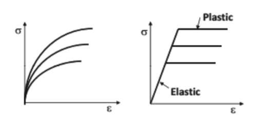 Figure 1. On the left - behavior of the soil, on the right - Mohr-Coulomb model's behavior
The failure plane is only dependent on normal stresses acting on the same axis. The criteria can be checked using angle of internal friction and cohesion on the Coulomb function and Mohr circle presented below. The software can simulate these parameters additionally changing them as depth rises.
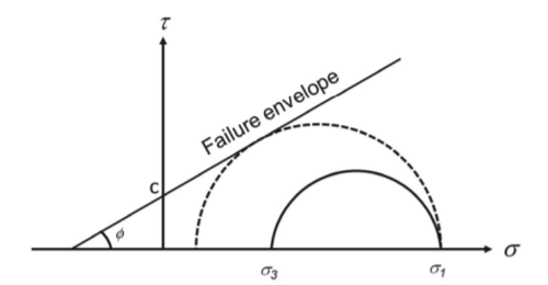 Figure 2. Stress state of failure criteria in Mohr-Coulomb model
The dilatancy angle is another parameter, used in Mohr-Coulomb model as volume increase in sheared soil. In cohesionless soils it leads to lowering the density of the soil. The move of the particles causes soil expansion in the axis perpendicular to the shear force acting on it. In cohesive soils the value is assumed as zero and in non-cohesive soils the value varies:
ψ = Φ - 30°
where:
ψ – dilatancy angle, in º
φ – angle of internal friction, in º.
However, the Mohr-Coulomb is only simplified model of the reality, so it has its disadvantages:
- In case of failure, the intermediate stress coefficient σ2 does not affect yield stress;
- The linear behavior of the Mohr’s circle does not fully translate the conditions;
- Angle of internal friction does not affect the hydrostatic pressure;
- High water pressure lowers the accuracy of computation;
- Compaction of soil is not included. However, the Mohr-Coulomb’s model is easy to use and describes the behavior sufficiently well.
The modification of Mohr-Coulomb plasticity model is response to inability of Coulomb’s theory to explain phenomena of compression, tension and torsion on brittle materials. It is particularly useful for geotechnical cases, where frictional materials like sand or concrete are used. Modified Coulomb-Mohr theory is a three-parameter theory, where these parameters can be derived by two simple tests.
In case of cast iron, there is close relationship between the cohesive resistance in shear and nominal ultimate strength in single or double shear. Theory also explains appearance of concavities in yield locus for different types of different matter.
Improvements to regular Coulomb-Mohr theory:
- Optional nonlinear elasticity;
- A smooth shear yield surface with a default Mohr-Coulomb approximation and with optional hardening/softening;
- An elliptical shaped compression yield surface with optional hardening;
- A dilatancy angle (related to the friction angle via Rowe's dilatancy rule) [2], [6], [7], [8].
3. Design Model
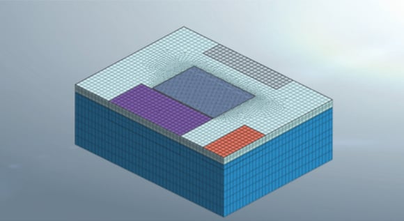
From the beginning there was a 2D geometry made in Midas. The software allows lines forming and shaping to obtain the geometry of the model. The geometry consisted of the surrounding buildings, boundary of the model and the excavation range in the middle. Then, the 2D geometry was meshed using quadrilateral elements. The excavation was most densely meshed in the middle, and further the distance from the middle, less dense the mesh is. The 2D mesh was then extracted to 3D non-uniformly to meet the certain depths of ground layers, bottoms of building and characteristic points. Then the extracted 3D mesh was divided into mesh sets consisting layers of the ground, diaphragm walls and other elements. [6], [7]
The different layers of the ground are presented in figures 4 to 7.
.jpg?width=580&name=Fig.%204.%20Man-made%20ground%20(excavation%20area%20marked%20in%20deeper%20blue%20color).jpg) Figure 4. Man-made ground (excavation area marked in deeper blue color)
Figure 4. Man-made ground (excavation area marked in deeper blue color)
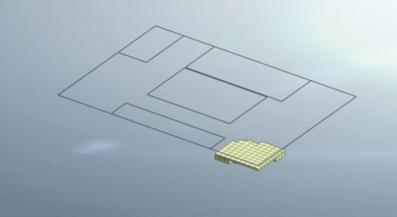 Figure 5. Clays with silts layer
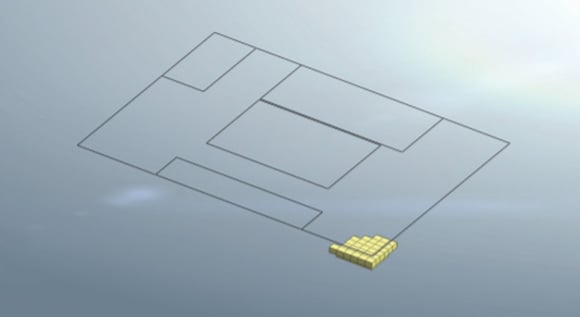 Figure 6. Fine sands layer
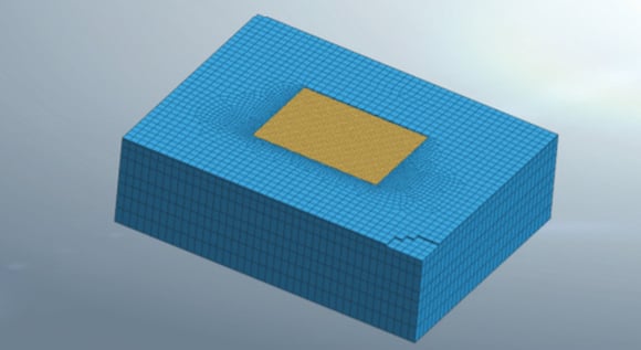 Figure 7. Poznan clays layer
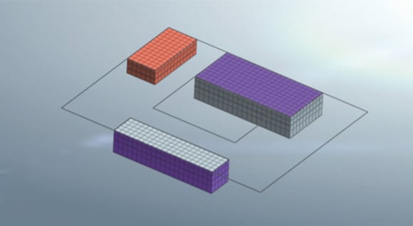 Figure 8. Surrounding buildings
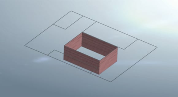
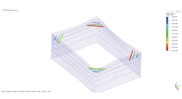
To obtain the best performance of diaphragm walls and prevent from collapsing struts were added. The struts modeled in this particular case are assigned to three cross-sections:
- Pipe – 406 mm x 12,5 mm;
- Pipe – 508 mm x 12,5 mm;
- Pipe – 711 mm x 12,5 mm.
The struts are localized in the corners of the cage to retain two adjacent walls and are made of S235 steel [3], [5].
The model of the strut system is presented in the Figure 10.
 Figure 10. Struts
Results
The analysis in Midas GTS NX software was performed to show stresses and displacements of diaphragm wall and the results are presented below in figures. In the software user can examine many types of results for each construction stages. For the purpose of this article the results presented were selected only from the last stage.
The results are divided into four main groups:
- Displacements;
- Bending moments;
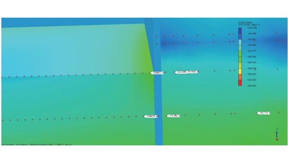
- Total solid stresses presented in two cross-sections;
- Axial forces in struts.
![Fig. 11. Displacements in the X direction [mm]](https://www.midasgeotech.com/hs-fs/hubfs/International_Geotech/blog/Fig.%2011.%20Displacements%20in%20the%20X%20direction%20%5Bmm%5D.jpg?width=580&name=Fig.%2011.%20Displacements%20in%20the%20X%20direction%20%5Bmm%5D.jpg) Figure 11. Displacements in the X direction [mm]
Figure 11. Displacements in the X direction [mm]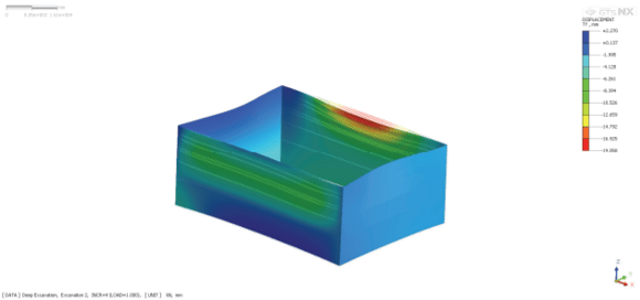
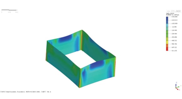 Figure 13. Shell force moments acting in XX direction [kNm/m]
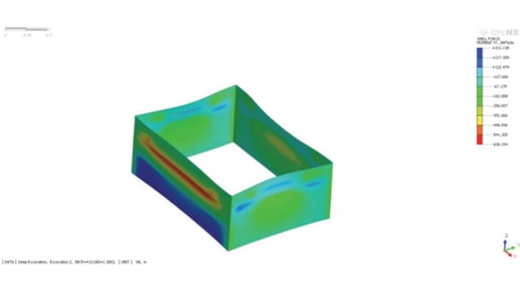
%20in%20XX%20direction.jpg?width=580&name=Fig.%2015.%20Cross-section%20of%20the%20model%20showing%20solid%20stresses%20(soil)%20in%20XX%20direction.jpg)
Analysis on Surrounding Objects
In the model, simplified surrounding buildings were included. Midas GTS NX allows user to have full control over the model, thus the results of the displacements and bending moments of the buildings can be seen. The Adjacent building is Andersia Hotel and the building on the other side is Novotel Hotel. The top slab is weightless to maintain the stiffness of the object. For the purpose of this article, displacements from the last stage of construction are presented below:
![Fig. 18. Displacements of the surrounding buildings in X direction [mm]](https://www.midasgeotech.com/hs-fs/hubfs/International_Geotech/blog/Fig.%2018.%20Displacements%20of%20the%20surrounding%20buildings%20in%20X%20direction%20%5Bmm%5D.jpg?width=580&name=Fig.%2018.%20Displacements%20of%20the%20surrounding%20buildings%20in%20X%20direction%20%5Bmm%5D.jpg) Figure 18. Displacements of the surrounding buildings in X direction [mm]
Figure 18. Displacements of the surrounding buildings in X direction [mm]![Fig. 19. Displacements of the surrounding buildings in Y direction [mm]](https://www.midasgeotech.com/hs-fs/hubfs/International_Geotech/blog/Fig.%2019.%20Displacements%20of%20the%20surrounding%20buildings%20in%20Y%20direction%20%5Bmm%5D.jpg?width=580&name=Fig.%2019.%20Displacements%20of%20the%20surrounding%20buildings%20in%20Y%20direction%20%5Bmm%5D.jpg) Figure 19. Displacements of the surrounding buildings in Y direction [mm]
Figure 19. Displacements of the surrounding buildings in Y direction [mm]![Fig. 20. Displacements of the surrounding buildings in Z direction [mm]](https://www.midasgeotech.com/hs-fs/hubfs/International_Geotech/blog/Fig.%2020.%20Displacements%20of%20the%20surrounding%20buildings%20in%20Z%20direction%20%5Bmm%5D.jpg?width=580&name=Fig.%2020.%20Displacements%20of%20the%20surrounding%20buildings%20in%20Z%20direction%20%5Bmm%5D.jpg) Figure 20. Displacements of the surrounding buildings in Z direction [mm]
Figure 20. Displacements of the surrounding buildings in Z direction [mm]After the final stage of excavation, the maximum displacements in X and Y direction are similar (15,5 mm in X and 12,3 in Y), however, the biggest displacements can be seen in the Z direction. The surrounding buildings were lifted up due to the construction of diaphragm walls and executing the excavation. The peak is close to 40 mm.
Summary and Conclusions
From the 1950’s popularity of diaphragm walls technology rises and growing number of objects benefit from its use. The example described in this article proves it, showing satisfying results of performance. During execution of the object, divided into four construction stages total solid stresses of soil, displacements and bending moments of the diaphragm walls were calculated in the software. Impact of the structure on surrounding buildings was observed.
Presented model was settled on mostly made ground and very cohesive clays typical for the region. The obtained results show importance of the struts, which took up large axial forces. The performance of the diaphragm wall would be even more sufficient with redesigned struts.
Overall impact of the diaphragm walls on the surrounding objects show biggest displacements in the vertical direction, lifting the buildings up. Horizontal displacements were relatively small and connected more with the pressure of the soil acting on the walls than with execution of deep excavation.
Model shows potential of the technology in terms of tunnel approaches, basements of high buildings, underpasses and many more underground objects. The conditions, as well as models of the buildings were simplified and in practice all actions concerning installation of such structures should be performed with extreme care.
Bibliography
[1] Clayton, C.R.I., Milititsky J., Woods, R.I.: Earth Pressure and Earth-retaining Structures. Second edition. London, Spoon Press, Taylor & Francis Group, 1993.
[2] Craig R.F.: Craig’s Soil Mechanics., London and New York, Spon Press Taylor&Francis Group, 2004.
[3] Boyes, R.G.H., Structural and cut-off diaphragm walls, London, Applied Science Publishers Ltd, (1975).
[4] Siemińska-Lewandowska, A.: Głębokie wykopy. Projektowanie i wykonawstwo, Warszawa, Wydawnictwa Komunikacji i Łączności, 2011.
[5] Puller, M.: Deep excavations: A practical manual, New York, Thomas Telford, 1996.
[6] Potts, David M., Zdravkovic L.: Finite Element Analysis in Geotechnical Engineering: Application. London, Thomas Telford Publishing, 2001.
[7] Midas GTS NX Manual: Chapter IV – Materials, MIDAS Information Technology Co.
[8] Midas GTS NX On-line Manual, MIDAS Information Technology Co., http://manual.midasuser.com/en_common/GTS%20NX/150/GTX.htm[9] EN 1997-1. Eurocode 7: Geotechnical design - Part 1: General rules, 2004.
[10] EN 1997-2. Eurocode 7 - Geotechnical design - Part 2: Ground investigation and testing, 2006.
[11] EN 1538:2010. Execution of special geotechnical works. Diaphragm walls, 2010.


👇 Watch the popular case study webinar
How to quickly master the geotechnical design report