The Application of Deep Mixing Method for a River Wall and Finite Element Simulation
🖱️ Click to jump
3. Constitutive Model Evaluation4. Finite Element Simulation5. Conclusion
Introduction
The ground improvement of the soft ground by mixing with cement is a very popular and effective method [3][2][1][7]. The stiffness, as well as strength of soft ground, can be improved by hydration and pozzolanic reaction between soil and cement [13]. The cement admixed clay (CA) is widely used in geotechnical projects, which are embankment [3], retaining structure [12] and foundation [8]. The stiffness increment of improved ground can reduce the unsatisfactory deformation of the project. The use of CA with retaining structure is very challenging for geotechnical engineers. The stress increment of this application is compression unloading stress condition, in which lateral stress decreases, and vertical stress is constant. Not only the challenge of increasing the state of stress but also the development of tensile stress in CA is also a very serious problem. The excessive tensile stress will create a crack in CA and create failure.
Finite element analysis was used to simulate and design CA to improve ground in many projects with different types of constitutive models. The simulation of both axial and lateral deep mixing of CA (DMC) has been done by 3-dimensinal finite element analysis by Voottipruex et al. [12]. The constitutive model of cement CA was elasto-plastic with Mohr-Coulomb as yield function (MCM). The constitutive model parameters were back-calculated from field testing results, which cause different parameter for each certain condition. For embankment simulation, the MCM with strain softening was used as a constitutive model for CA for simulating the behaviours of the embankment by Yapage et al. [8].
The consolidation analysis successfully simulated the embankment settlement. The behaviour of CA improved slope was analysis with the finite elements by Jamsawang et al. [10]. The model for CA was MCM. The factor of safety was also analyzed by finite element analysis. The behaviour of the retaining structure was also simulated by finite element analysis by Jamsawang et al. [11]. The elastoplastic model with both kinematic and isotropic hardening, which is Hardening Soil Model (HSM), was used to model the behaviors of CA. The model parameters were obtained by curve fitting from element test by undrained triaxial and oedometer tests. From overall literature, the finite element analysis of the deep mixing method (DMM) used elasto-plastic model with and without hardening features to simulate the behaviours of CA.
The question might arise whether these constitutive models are suitable for simulation with other stress paths like compression unloading. The gap in research was the simulation of CA with different stress paths with the aforementioned constitutive model. The limitations and evaluation of constitutive models need to be studied.

This paper presents the behaviours of using the deep mixing method (DMM) to improve the stability and serviceability of a river wall. The main objective of this wall is for dredging proposed to enlarge a water channel of the river. The construction sequence and its behaviour are discussed in this paper. Moreover, the 3-dimensional finite element analysis was used to simulate the wall behaviour. The evaluation of constitutive models with different stress paths is discussed. The comparison of the stress response envelop of test results and model prediction is presented. Then, the simulation of the river wall with DMM was done by using GTX NX software.
Overall, the contributions of this work can be listed as follows:
1) The effectiveness of different types of a constitutive model for CA was assessed with a stress path triaxial test, which has compression loading and unloading. The stiffness predictions of the different constitutive models were accessed by their response envelop.
2) The construction procedure and behaviours of the river wall improved with CA were presented.
3) The numerical technique and procedure for simulating an application of CA as a retaining structure were proposed. This might be an initial guideline for a simulation and design of using CA in a river wall.
Project Information
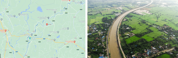 Image 1. Pasak River
Pasak River is a major river in central Thailand for water transport. It locates 100 kilometers northern part of Bangkok. Due to the shallow current channel, the riverbed needs to be dredged to increase the river channel. The stability of the river bank had to be improved by a soil-cement column as shown in Fig. 1. The front of the wall was a sheet pile to improve the stiffness and erosion resistance of the system. The arrangement of the cement column was a honeycomb pattern to increase its moment of inertia of improved area and cost-effectiveness.
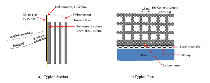 Figure 1. The typical cross-section of deep mixing of cement admixed clay improved the riverbank
During the construction stage, the soil at the front wall was excavated for more space for water transportation on the river. The stress state of cement admixed clay is reduced in a lateral direction called ‘compression unloading’. The stress increase is not only compression unloading, but some part also has different stress increase status such as compression loading. The inclinometer was installed in the DMM near the sheet pile at the front face of the wall.
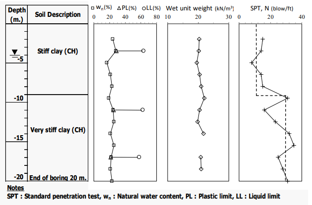 Figure 2. Soil profile
The soil profile of this project consists of stiff clay and very stiff clay from a depth of 20 meters as shown in Fig. 2. The standard penetration value (SPT-N) tends to slightly increase with depth. The water content of the soil was relatively uniform through the investigation borehole. The groundwater level is similar to water in the river 5 m from the ground surface. The initial water content of the soil is near its plastic limit cause have high strength and stiffness.
The soil type is high plasticity clay due to its high liquid limit, which is more than 50%. Mixing cement with clay is difficult because of its high plasticity when the total soil water content is between the liquid and the plastic limit. The deep mixing with high pressure was first selected to ensure the bonding destroy before adding cement for mixing. However, the high pressure of the jet caused the movement of the sheet pile wall. The low pressure with mechanical mixing was used at the DMM near the sheet pile wall.
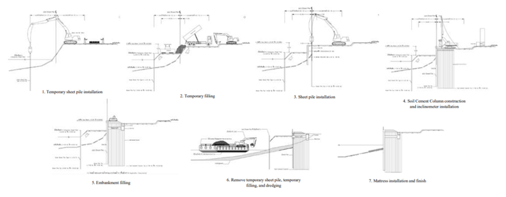 Figure 3. The construction sequence river wall
The construction sequence begins with installing a temporary sheet pile in front of the proposed wall in the river, as shown in Fig. 3. Then, the permanent sheet pile was installed for use as a wall face. The DMM was then constructed behind the sheet pile wall. Some part of DMM was blocking to building drainage of groundwater to a front wall. After the strength of DMM increased to an expected value, the embankment was built on DMM with a sidewalk for the cycling track. Finally, the soil in front of the pile of sheets was removed by the excavator on a riverboat.

Constitutive Model Evaluation
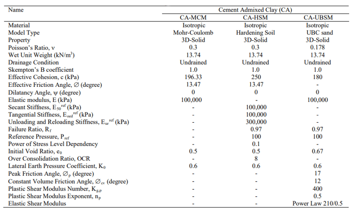 Table 1. Constitutive model parameters of cement admixed clay
Before performing full finite element simulation, we calibrate the constitutive model parameters for CA with different models, which are elasto-plastic with Mohr-Coulomb as yield function (MCM), hardening soil model (HSM), and UBC-Sand Model (UBSM) [4][9]. The MC model has one fix yield function without a hardening feature. When the stress state reaches the yield criteria, the dilatancy characteristic, which is contraction and dilation, is controlled by a dilatancy angle, ψ.
This simulation assumed to be zero dilatancy caused no change of excess water pressure after yield. The MCM and UBSM have 2 hardening yield functions, which can move according to changing deviatoric and volumetric strains. The dilatancy characteristics of UBSM were controlled by the difference between mobilized friction and constant volume friction angle. The model parameter for each model was curve fitting from the test result as shown in Table 1. The model parameters of MCM were in a similar range to the previous research [12]. The elastic modulus of this study was a bit higher than the previous due to a higher cement content.
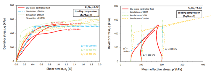 Figure 4. Stress-strain and stress paths of CIU test results and constitutive model simulations
The results from the constitutive model simulation are shown in Fig. 4. We perform the stress-strain simulation by using the “Soil Test” subroutine in GTS NX program. The program feature could help calibrate the model parameters before conducting full finite element analysis. The stress-strain increment was set to be an undrained triaxial compression test, which increases vertical strain with constant lateral stress. The set of parameters was biased to match the q-es relationships more than predicting excess pore water pressure to minimize the prediction error. UBSM performs the best performance with other models for simulation of q and es.
It can simulate the nonlinear behaviours of test results after q being more than 400 kPa. MCM and HSM were over-predicting the value of q. For the q-p stress path prediction, MCM shows the best prediction compared to another model. The excess pore water pressure is initially positive and then does not significantly change after it reaches the yield condition. The UBSM and HSM overpredicted the excess pore water pressure that has the value of mean stress being lower than the actual test results.
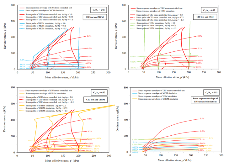 Figure 5. Stress response envelope of CIU test results and simulation with MCM, HSM, and U
The performance of each constitutive model with a different stress path was present by its stress response envelope as shown in Fig. 5. The stress response envelope is the response of stress by a certain magnitude of strain [4][9]. The higher stress level of the model showed the higher stiffness. The model performance is compared with the test results obtained from the triaxial stress path of CA by Makararotrit et al. [15]. The stiffness of CA predicted by MCM is higher than that of test results when mean stress was lower than 70 kPa for considering strain level at 0.1%. The predicted stiffness at the high mean was overall higher than the test results. The performance of UBSM was higher than HSM.
Overall, predicted stiffness overestimated test results when having low mean stress or compression unloading stress conditions. The effective constitutive model for CA is required to predict for overall stress state and stress path. The model parameters of each model were based on back-calculation or curve-fitting the results. The bias of the parameters might occur. Systematic optimization by using particle swarm [5] optimization or genetic algorithm [14] might be required to reduce the error of the prediction.
Finite Element Simulation
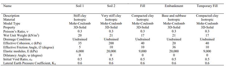 Table 2. Constitutive model parameters
The behaviors of the DMM river wall were simulated with 3-dimensional finite element analysis. The program Midas GTS NX was used for simulation. We simplified the 1.5 meters width of the wall for analysis. The finite mesh for this study is shown in Fig. 6. The element type of the analysis was 20 node hexahedrons [6]. Mesh of an analysis composed of 11,059 elements and 58,518 nodes. The boundary condition was set to be fixed at the bottom of mesh and have a vertical degree of freedom on every side of the mesh. The effect of the boundary condition was checked by enlarging mesh size to have no effect on the analysis result. The water level was set to be constant during the time of construction and monitoring. The water level at the site was not changed due to the water management of a dam on the water upstream. The river wall simulation was divided into 4 stages that consisted of 1. Initial stage 2. Embankment filling and 20 kPa surcharge on the embankment 3. Temporary filling and temporary sheet pile were removed 4. Dredging and 5. Mattress installation.
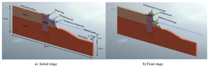 Figure 6. 3-dimensional finite element mesh
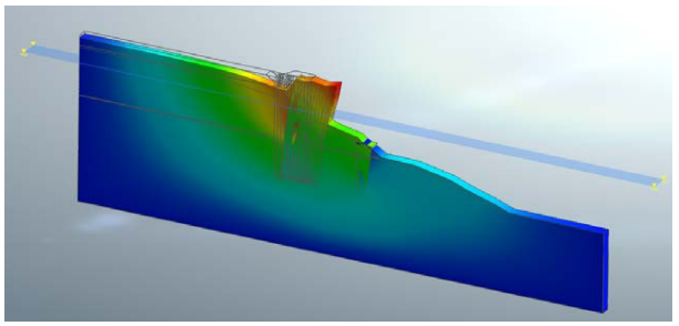 Figure 7. Deformation of river wall from finite element analysis
The comparison between finite element analysis and field measurement of wall movement is shown in Fig. 8. The wall was moved to the river direction due to unloading by dredging. The largest movement occurred about 80 mm at the top of the wall. The lateral movement decreased with depth and no movement 15 meters from the ground surface. The MCM showed the best performance to predict the lateral wall movement. The prediction obtained from HSM and UBSM underpredicted the wall movement from 0 to 7 from the ground surface. The wall prediction results performance could be explained by the stress response envelop in Fig. 5.
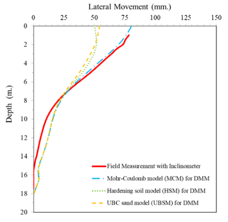 Figure 8. Comparison between field monitoring and finite element simulation
The performance of the constitutive model to predict triaxial test results is good with high confining stress (p > 70 kPa). The results conform to the finite element prediction that the forecast was agreed with monitoring results when mean stress was more than 70 kPa or depth was more than 6 m. The stiffness of the MCM model was the lowest one and lower than that of UBSM and HSM.
Conclusion
The behaviours of the river wall improved with cement admixed clay as well as finite element simulation was presented. The conclusion can be made as follow:
1) MCM dementated the best performance to capture the stress-strain relationship of CA from the triaxial test compared to UBCM and HSM. UBSM and HSM overpredicted the pore water pressure from triaxial tests.
2) According to the response envelope, the predicted stiffness tends to overestimate the test results.
MCM showed the best performance among UBSM and HSM.
3) A three-dimensional finite analysis was successfully used to predict the river wall movement. The prediction underestimated the field measurement with low mean stress.
4) The best constitutive model for DMM in finite element analysis was MCM. When using HSM and UBCM for CA, the result of finite element underpredicted the field measure.
*Acknowledgments
The authors would like to thank MIDAS Co., Ltd. for providing the license of analysis software.
References
[1] A. Porbaha, “State of the art in deep mixing technology: part I. Basic concepts and overview,” Proc. Inst. Civ. Eng.
Improv., vol. 2, no. 2, pp. 81–92, 1998.
[2] D. A. Bruce, “Practitioner’s guide to the deep mixing method,” Proc. Inst. Civ. Eng. Improv., vol. 5, no. 3, pp. 95–100, 2001.
[3] D. T. Bergado, T. Ruenkrairergsa, Y. Taesiri, and A. S. Balasubramaniam, “Deep soil mixing used to reduce
embankment settlement,” Proceedings of the ICE - Ground Improvement, vol. 3, no. 4. Thomas Telford, pp. 145-145-
162–162, Oct. 01, 1999, doi: 10.1680/grim.1999.3.4.145.
[4] H. Puebla, “A Constitutive Model for Sand and the Analysis of the CANLEX Embankments,” Ph.D. Thesis, 1999.
[5] J. Sadoghi Yazdi, F. Kalantary, and H. Sadoghi Yazdi, “Calibration of Soil Model Parameters Using Particle Swarm
Optimization,” Int. J. Geomech., vol. 12, no. 3, pp. 229–238, 2012, doi: 10.1061/(asce)gm.1943-5622.0000142.
[6] Midas, “Midas GTX NX Analysis Manual,” 2020. doi: 10.4324/9781315010335-12.
[7] M. Kitazume and M. Terashi, The deep mixing method, vol. 21. CRC press Boca Raton, FL, USA:, 2013.
[8] N. N. S. Yapage, D. S. Liyanapathirana, R. B. Kelly, H. G. Poulos, and C. J. Leo, “Numerical Modeling of an
Embankment over Soft Ground Improved with Deep Cement Mixed Columns: Case History,” J. Geotech.
Geoenvironmental Eng., vol. 140, no. 11, p. 04014062, 2014, doi: 10.1061/(asce)gt.1943-5606.0001165.
[9] O. Library, I. Society, S. Mechanics, G. Engineering, and D. Committee, “Effect of Mean Stress Dependency of Elastic Soil Moduli on the Constitutive Behavior of Sand through UBCSAND,” in 26th European Young Geotechnical Engineers Conference, 2018, pp. 225–234.
[10] P. Jamsawang, P. Voottipruex, P. Boathong, W. Mairaing, and S. Horpibulsuk, “Three-dimensional numerical investigation on lateral movement and factor of safety of slopes stabilized with deep cement mixing column rows,” Eng. Geol., vol. 188, pp. 159–167, 2015, doi: 10.1016/j.enggeo.2015.01.017.
[11] P. Jamsawang, P. Voottipruex, P. Tanseng, P. Jongpradist, and D. T. Bergado, “Effectiveness of deep cement mixing
walls with top-down construction for deep excavations in soft clay: case study and 3D simulation,” Acta Geotech., vol.
14, no. 1, pp. 225–246, 2019, doi: 10.1007/s11440-018-0660-7.
[12] P. Voottipruex, T. Suksawat, D. T. Bergado, and P. Jamsawang, “Numerical simulations and parametric study of SDCM and DCM piles under full scale axial and lateral loads,” Comput. Geotech., vol. 38, no. 3, pp. 318–329, 2011, doi:
10.1016/j.compgeo.2010.11.006.
[13] S. Horpibulsuk et al., “Water-Void to Cement Ratio Identity of Lightweight Cellular-Cemented Material,” J. Mater.
Civ. Eng., pp. 1–10, 2014, doi: 10.1061/(ASCE)MT.1943-5533.0001110.
[14] S. Pal, G. W. Wathugala, and S. Kundu, “Calibration of a Constitutive Model Using Genetic Algorithms,” Comput.
Geotech., vol. 19, no. 4, pp. 325–348, 1996, doi: 10.1016/S0266-352X(96)00006-7.
[15] W. Makararotrit, S. Youwai, and P. Rodpol, “Deformation characteristics of cement treated pasak clay and bangkok
clay with different stress path,” World Congr. Civil, Struct. Environ. Eng., no. April, 2019, doi: 10.11159/icgre19.192


- Blog | How to define the construction sequence
- Blog | Design of 20m Deep Excavation with Permanent Anchored SBPW and CBPW