Finite element modeling of slope wall stabilizer by nail and anchors
🖱️ Jump to the contents (Click)
1. Introduction
Introduction
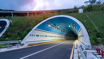
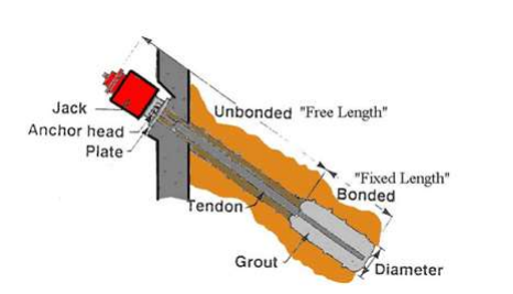
Anchored walls have become popular in braced excavations because of a) the substantial progress in the technology and availability of high-capacity anchor systems, and b) the absence of interior obstructions that permit uninterrupted earth moving and thus improve the construction conditions of the underground portion of a building (Xanthakos, 1994). Figures 1 and 2 show a photo and a schematic of tied-back slurry wall excavations. In some projects, tiebacks have been used in combination with rakers and soil berms and/or corner braces (Gnaedinger et al., 1975). Tieback anchors comprise a barrel anchorage located either in a bearing layer that is tensioned at the front face of the wall. The part of the anchor that transfers the force to the surrounding soil is frequently called the "fixed length", while the "free length" transmits forces from the fixed length through the anchor head to the slurry wall.
In order to minimize wall movement and ground settlement, tieback anchors are designed to achieve the highest stiffness possible within economical considerations. Tieback capacity depends on the vertical and horizontal spacing of anchors and on surcharge conditions. Prestress levels typically range from 40 to 250 kips when the grouted portion of tiebacks is within soil; higher loads are used when the ties are installed within the bedrock. Typical tieback spacing ranges from 7ft to 13ft in the vertical direction, and from 5ft to 15ft in the horizontal direction (from the current database). Tieback capacity is reduced if the spacing is too close due to interference between adjacent grouted zones.
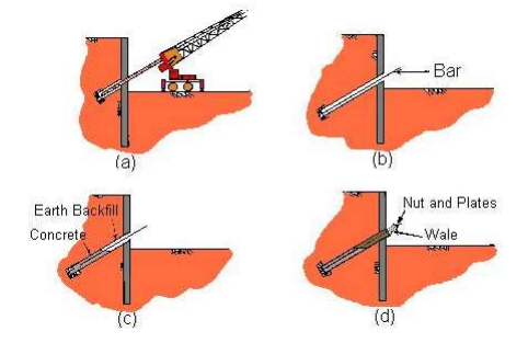
(a) hole drilled; (b) bar placed in hole; (c) concrete poured for
anchor; (d) wall connection made (Adapted from Schnabel, 1982).
Project Information
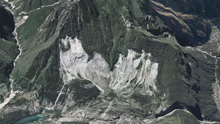
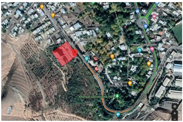
Geotechnical studies were carried out at the Zagros Khansar Hotel, located in Khansar (Shown in Figure 3), Iran in April 2021. These studies, in terms of having previous information about the geological, hydrological and geotechnical conditions of the project area and the results of surveying two research boreholes at depths of 25 and 20 meters above the ground at the Zagros Khansar Hotel and collecting, reviewing, processing and Data analysis from studies in the region was performed. An overview of the information of one of the drilled boreholes indicates the existence of subsurface layers including:
In BH1 borehole: up to 3 m deep poorly graded gravels with clay (GP-GC), From a depth of 3 to 6 meters, the olive shale rock is completely transformed (aerated) and crushed to the extent of sand and rubble, and finally, from a depth of 6 meters to 25 meters, the ground material includes olive and gray mass shales in Some depths turn to broken rock.
The building will be constructed on land with an approximate area of 1400 square meters with dimensions of 56 x 25 meters.
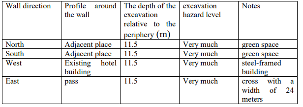
The next step is the execution of the excavation. Dimensions of the excavation are connected with the equipment used. The most commonly used width varies from 50 to 100 cm, and its length is usually no longer than 6 meters. As the excavation proceeds, there is supporting suspension brought inside. Slurry prevents the excavation from collapsing. Many types of machines are used to deepen the excavation, but the most common are the drilling grabs. Vertical excavation without stabilization of soil and stone, if there are joints and cracks, the excavation is completely unstable and the maintenance of the pit walls in the construction site requires the construction of a guard structure. The risk assessment of the pit in each of the walls of the construction site, taking into account the groundwater level and the possibility of water leakage from the walls is presented in Table 1.
In-Situ tests were performed with Dynamic Cone Penetration Test. There was a limited program of laboratory tests (index properties, water content and Triaxial Compressive Strength test, and particle size distributions) while permeability properties were reported from lugeon tests. The dynamic characteristics of the rocks in the area can be calculated based on the results of downhole seismic testing and existing relationships. Based on the information obtained from the drilling of the exploratory borehole in this project, underground water (surface water) has been encountered at a depth of approximately 7 meters from the surface of the earth.
This modeling was done using Midas GTS NX finite element software; GTS NX is finite element analysis software for advanced geotechnical analysis of soil and rock deformation and stability, as well as groundwater flow, dynamic vibrations and soil-structure interaction in 2D and 3D. GTS NX is used for analysis, testing, and design by geotechnical, civil, and mining engineers. It is designed to adapt to any kind of geotechnical project. The intuitive interface will enable new users to easily integrate the software
in their work process.
According to the geotechnical model of the design construction and using soil design data, the stability of the slope walls in natural conditions (without soil improvement), with a safety factor of 0.387 was analyzed.
According to the stability analysis results and the safety factor for the overall stability of the temporary excavation is equal to 1.3, vertical excavation without stabilization of soil and rock, if there are joints and cracks in the slope wall is completely unstable and maintaining this requires the retaining system.
Phased excavation: maximum depth of 2 meters. In the running soil layers, excavating in a sloped manner (ramp) with a ratio1:1 is done. After this step, the walls are fixed vertically.
- Regulating the surfaces of the walls and leveling the work sections after the excavation operation, the work surfaces are leveled manually or with an excavator.
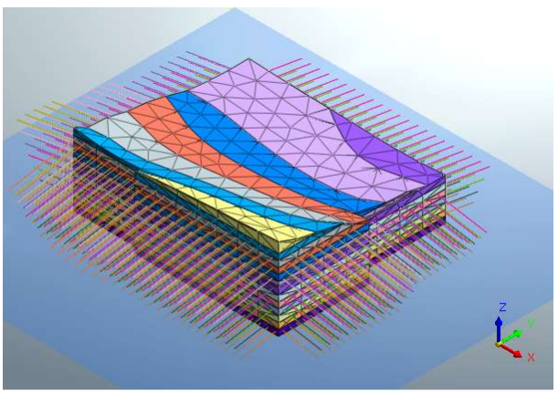
- Installation of nails and strands and their injection: the matrix of nails and anchors is installed on the wall based on the plans provided. After installing the bolt or rebar and strand, the injection operation around the nail and the length of the anchor bond is done according to the announced instructions.
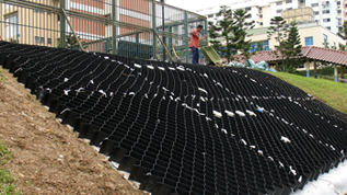
- Installation of metal meshes and drains: Reinforcement grids are prepared and installed on the wall and ready for shotcrete. In order to keep the meshes on the wall, the meshes are fastened to the wall in several areas by means of metal nails. Before installing the meshes, engineering drains are installed
with horizontal distances of 5 meters from each other.
- Implementation of the final shotcrete: in this step, a layer of shotcrete with a thickness of 10 cm was made according to the technical specifications mentioned in the agenda. In the implementation of shotcrete, both dry and wet methods can be used. Installation and injection of nails and anchors can be done after the completion of the final shotcrete. There is no need for mesh and shotcrete in the parts that have been excavated on a slope.
- Installation of the end plates and installation of the bead and completion of the nails: with the installation of the designed steel plate along with the bead, the nails are practically completed and the next stage of operation can be started.
- Pre-stress Test
Bearing plate, wedge plates and the anchor head are placed on the anchor, minimum 7 days after its completion. The anchor strand should extend outwards 90-100 cm from the front face of the soldier beam. By the means of using the hydraulic jack with the power unit, readings are taken at 25, 50, 75, 100 and 125% of the design load. Deformations are read likewise with a measuring scale and recorded. The load will eventually be decreased back to the design load, the anchors are locked at the prespecified design load.
- The above steps are repeated for every 2 meters of depth (maximum 2 meters) and until the desired level is reached.
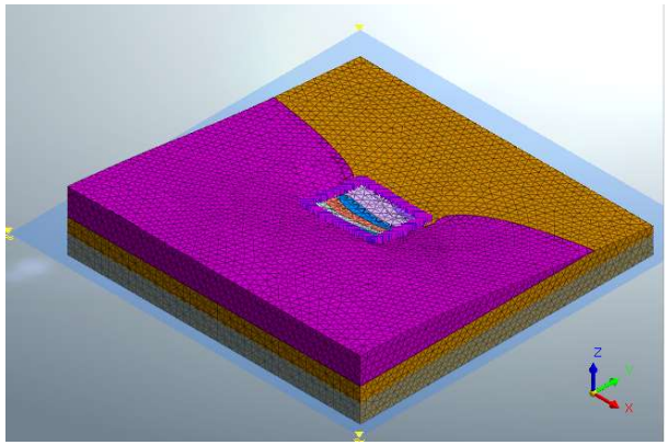
In this project, the maximum excavation depth is 27 meters, the wall slope is stabilized with nails and anchors. The stabilized area is 4813.23 square meters with 8713 m anchor 64 m nail.
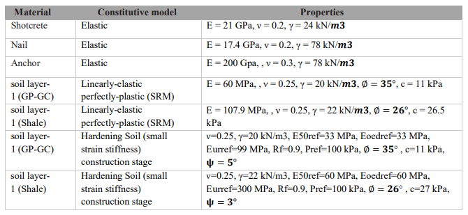
At first, the stability analysis of the slope (SRM) was performed, and then construction stage analysis was used to obtain stress values and deformations. For the first analysis, The constitutive model of ground and excavation were elastoplastic with Mohr-Coulomb as yield function (MCM) and Shotcrete, Nails and Anchors were modeled as an elastic material. All the material properties used in this study are summarized in Table 1. The soil hardening model is used for ground in the analysis of the construction stage.
Conclusion
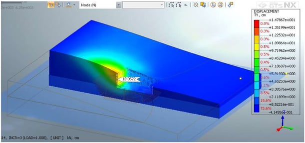
In the construction stage analysis, As shown in Figure 6 the maximum lateral deformation that occurred on the western side of the slope wall was 12 cm. Also, the safety factor obtained from slope stability analysis was 1.537, which is almost equal to the allowed safety factor declared by the Iranian construction engineering organization.
There is a road on the southwest side of the excavation and the ground surface is flat, therefore the load and deformation are less than the value obtained in the software. Also, according to the plan in Figure 3, there are no buildings sensitive to deformation on the side of the excavation, so the lateral deformation obtained is within the permissible range.
Reference
1- Xanthakos, P. P., Abramson, L. W., & Bruce, D. A. (1994). Ground control and improvement. John Wiley & Sons.
2- Gnaedinger, J. P., Gill, S. A., & Keim, P. A. (1975). Performance of tied-back excavation at Water Tower Place. ASTM International.
3- Kannan, R., & Broms, B. B. (1984). Use of Ground Anchors in Residual Soils. In First international conference on case histories in geotechnical engineering (1984: May 6-11; St. Louis, Missouri). Missouri S&T (formerly the University of Missouri--Rolla).