🖱️ Jump to the contents
1. Introduction
4. Foundation Conditions
5. Loading Combinations
6. Loading Combinations
7. Finite Element Modelling And Analysis
(Download E-Book for free to see all contents)
👉 Case Study Webinar

Olifantspoort Dam
Introduction
The Olifanstpoort Dam comprises an off-channel storage facility to be constructed near the Olifantspoort water abstraction works on the Olifants River in Polokwane, South Africa.
The owner of the dam is Lepelle Water acting on behalf of the South African Department of Water and Sanitation. ARQ was consulted as specialist dam engineers for the design work forming part of the refurbishment and upgrading of existing raw water abstraction works at Olifantspoort.
The dam has been designed as a ring structure incorporating five enclosure walls to enclose a valley to the west of the abstraction weir. The southern portion of the dam structure is the highest of the ring components and it comprises a 22 m high Rubble Masonry Concrete (RMC) multiple-arch buttress dam, with a crest length of 230 m. ARQ has been involved in the design of 17 RMC dams constructed in Southern Africa ranging from 9m to 42 m in height.
The southern portion of the ring structure is made up of arches with varying radius sizes as shown in Figure 1 and Figure 2. The varying arch sizes were implemented to account for changing foundation conditions under the dam footprint. The buttress portion of the dam transfers most of the load to the foundation, so it was deemed suitable to find the buttresses on the most competent portions of the dam footprint. To achieve this a customized span and radius size were adopted for arches between buttresses placed accordingly.
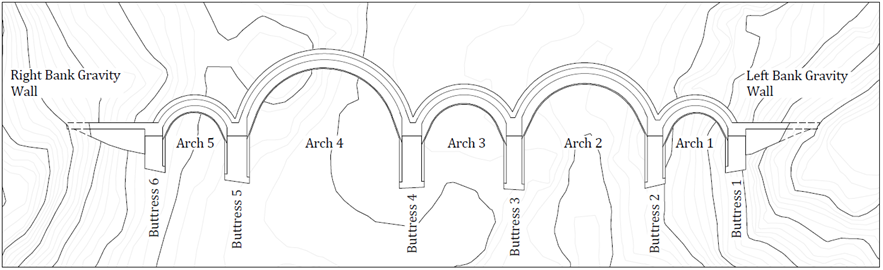
Figure 1. Plan view of dam southern wall configuration
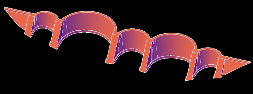
Figure 1: Isometric view of the 3D CAD model of dam body
Design Approach
The arch and buttress components of the dam configuration were initially designed and analyzed for sliding and overturning stability according to a limit equilibrium approach, assuming the rigid body motion of the dam. Cylindrical arch and elementary beam theory were assumed to determine the required thickness of the arches and buttresses, according to allowable stress criteria.
These assumptions do not consider the flexibility of the dam structure resulting in rib-shortening and other geometrical changes due to deflection of the dam under loading. The effect of long-term temperature drop load can also not be analysed using limit equilibrium hand calculations.
The initial geometrical configuration derived using the limit equilibrium approach was refined further by undertaking FE (finite element) analysis studies on the dam-foundation structure using Midas FEA NX analysis software. The results of the FE analyses allowed for the structural behaviour of the dam to be evaluated and to ensure an efficient stress transfer of loads. This is achieved by minimizing upstream cantilever tensions, maximizing upstream arch compressions, and limiting downstream vertical bursting stresses.
The results computed by the FE analysis were evaluated against applicable design criteria.
Three primary failure modes of the dam were postulated and reviewed in terms of design criteria, these comprise:
- Global overturning stability
- Sliding stability at the interface between base and foundation
- Structural material failure of the dam due to internal stress development
Design Criteria
RMC is a composite material comprising a matrix of large stone or plums in mortar binder. The stone sizes range from 50 mm – 300 mm diameter and should be less than one third of smallest dimension of dam. The mortar binder constitutes a one-part cement and four-part sand mix with a design strength of 14 MPa (Rankine et al, 1999). The performance of the RMC material is highly reliant on its stone-mortar composition. The ideal mix of stone and mortar is shown in Figure 3.
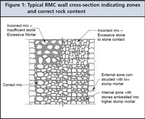
Figure 4. RMC stone-mortar composition (CIDB, 2005)
Typically, the performance of the mortar, as the weakest component of the matrix, is assumed. To estimate the tensile strength of RMC, the same relative behaviour characteristics as applicable for conventional mass concrete were accordingly accepted.
In view of the limited knowledge of RMC’s performance characteristics, low stress levels in relation to assumed strength were adopted (Shaw, 1998).
Considering the above, the criterion aims at restricting the resultant compressive stress intensity to the degree that ensures a linear elastic materials behaviour. This permissible stress is conservatively estimated as 0.35 ƒcu. On this basis, the allowable compressive stresses indicated in the analyses are accordingly limited to 4.9 MPa.
In the absence of testing, the tensile strength of concrete is commonly approximated based on the mix compressive strength, for which a factor of 0.1 ƒcu is generally assumed, implying tensile strengths of 1.4 MPa.
However, permissible stresses are usually set lower in the case of masonry than for concrete. For the purpose of this design, tensile stresses are limited to 0.4 MPa under usual and unusual loading conditions and to 0.6 MPa, under extreme loading combinations.
The required design criteria for the loading conditions are provided in Table 1.
|
Loading Condition |
Compressive Strength |
Tensile Strength |
|
Normal |
0.35 * fcu = 4.9 MPa |
0.3 * ft = 0.4 MPa |
|
Unusual |
0.35 * fcu = 4.9 MPa |
0.3 * ft = 0.4 MPa |
|
Extreme |
0.45 * fcu = 6.3 MPa |
0.45 * ft = 0.6 MPa |
Table 1. RMC Design Criteria for Olifantspoort OCSD
📙 Want to read more?

.png?width=737&name=bio_Ryan%20Cassells(2).png)
👉 Case Study Webinar