🖱️ Jump to the contents
1. Introduction
2. Limited Equilibrium Method (LEM)
- Background and history
- Fundamentals
- General Limited Equilibrium Method
3. Finite Element Method (FEM)
- Overview
- Strength Reduction Method (SRM)
- Advantages of the Finite Element Method
4. Conclusions
>> Related expert's column

Comprehensive Slope Stability Analysis and Design (LEM vs FEM)
Slope stability is a precise significant problem in geotechnical engineering. Slope stability investigation using computers is an easy task for engineers when the slope outline and the soil parameters are known. However, the choice of the slope stability investigation method is not an easy task and effort should be made to collect the field circumstances and the failure observations in order to appreciate the failure mechanism, which determines the slope stability method that should be used in the analysis. Two-dimensional slope stability methods are the most commonly used methods among engineers due to their straightforwardness. Today, both limit equilibrium method (LEM) and finite element method (FEM) based software are commonly used in geotechnical computations.
Introduction
Techniques for investigating the safety of slopes incorporate basic conditions, outlines, spreadsheet programming, and slope stability PC programs. As a rule, more than one technique can be utilized to assess the safety of a specific slope. For more refined investigations and complex slope, soil, and stacking conditions, PC programs are by and large used to play out the calculations. PC programs are accessible that can deal with a wide assortment of slope geometries, soil stratigraphy’s, soil shear quality, pore water weight conditions, outside burdens, and inside soil fortification. Most projects additionally have abilities for consequently hunting down the most basic slip surface with the least factor of safety and can deal with slip surfaces of both roundabout and non-roundabout shapes. Most projects likewise have designs abilities for showing the information and the aftereffects of the slope stability calculations.
Once the different methods of disappointment are distinguished, a technique for examination ought to be embraced to survey the steadiness of the slope. There are two essential ways to deal with steadiness investigation: The limit equilibrium method (LEM) and the Finite element method (FEM). The primary distinction between these two investigations approaches is that the LEM depends on the static of harmony while FEM uses the stress‐strain relationship or constitutive law.
Limit Equilibrium Method (LEM)
1. Background and history
Limit equilibrium types of analysis to assess stability have been used in geotechnical engineering for decades. The concepts have been widely applied to the stability analysis of earth slopes. The idea of discretizing a potential sliding mass into vertical slices was introduced early in the 20th century. In 1916, Petterson (1955) presented the stability analysis of the Stigberg Quay in Gothenberg, Sweden where the slip surface was taken to be circular and the sliding mass was divided into slices.
During the next couple of decades or so, Fellenius (1936) introduced the Ordinary or Swedish method of slices. In the mid-1950s, Janbu (1954) and Bishop (1955) developed advances in the method. The advent of electronic computers in the 1960s made it possible to more readily handle the iterative procedures inherent in the method, which led to mathematically more rigorous formulations such as those developed by Morgenstern and Price (1965) and by Spencer (1967).
The introduction of powerful desktop personal computers in the early 1980s made it economically viable to develop commercial software products based on these techniques, and the ready availability today of such software products has led to the routine use of limit equilibrium stability analysis in geotechnical engineering practice.
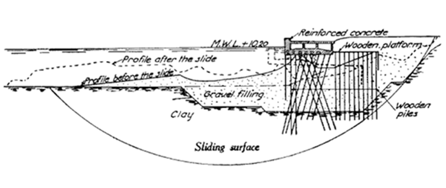 Figure 1. The Stigberg Quay, sliding surface, 1916
(80m from the east end of the wall)
Modern limit equilibrium software is making it possible to handle ever-increasing complexity in the analysis. It is now possible to deal with complex stratigraphy, highly irregular pore-water pressure conditions, various linear and nonlinear shear strength models, almost any kind of slip surface shape, concentrated loads, and structural reinforcement. Limit equilibrium formulations based on the method of slices are also being applied more and more to the stability analysis of structures such as tie-back walls, nail or fabric-reinforced slopes, and even the sliding stability of structures subjected to high horizontal loading arising, for example, from ice flows.
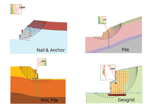 Figure 2. Structural reinforcements for slope stability analysis
While modern software is making it possible to analyze ever-increasingly complex problems, the same tools are also making it possible to better understand the limit equilibrium method. Computer-assisted graphical viewing of data used in the calculations makes it possible to look beyond the factor of safety. For example, graphically viewing all the detailed forces on each slice in the potential sliding mass, or viewing the distribution of a variety of parameters along the slip surface, helps greatly to understand the details of the technique. From this detailed information, it is now becoming evident that the method has its limits and that it is perhaps being pushed too far beyond its initial intended purpose. Initially, the method of slices was conceived for the situation where the normal stress along the slip surface was primarily influenced by gravity (weight of the slice). Including reinforcement in the analysis goes far beyond the initial intention.
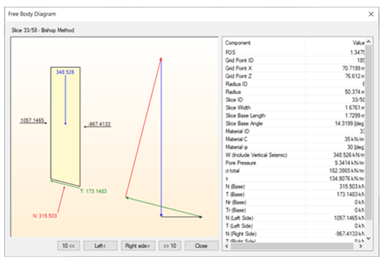 Figure 3. Slip surface details with a free body diagram
2. Fundamentals
It seems that the fundamentals of the limit equilibrium method of slices are not well understood, despite the routine use of the method in practice. The fact that the limit equilibrium method of slices is based on nothing more than statics often seems to be forgotten, and the significance of one factor of safety for all slices is not appreciated. In order to use the limit equilibrium method effectively, it is useful to have a good understanding of the formulation fundamentals.
The formulation is based on principles of limiting equilibrium. It means that forces on a free body are such that it will remain stationary. It satisfies statics, and the summation of moments, horizontal forces, and vertical forces is zero. There are some important assumptions as in the below:
- The factor of safety is a constant along the slip surface.
- Each slice has the same factor of safety.
- The factor of safety is defined as the factor by which the soil strength must be reduced so that the potential sliding mass is a point of limiting equilibrium. That is, the moments and forces must sum to zero.
This figure illustrates a typical slice in a potential sliding mass with the forces acting on the slice. Normal and shear forces act on the slice base and on the left and right sides of the slice.
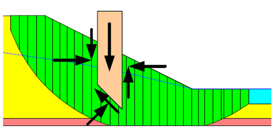 Figure 4. Slices and forces in a sliding mass
3. General limit equilibrium method
Various solution techniques for the method of slices have been developed and are in common use. The primary difference among all these methods lies in which equations of statics are considered and satisfied, which interslice normal and shear forces are included, and the assumed relationship between the interslice forces. This table summarizes the conditions for some of the common methods. This table lists which equations of equilibrium are satisfied, whether the interslice normal is included, whether the interslice shear is considered, and what the assumed relationship between the interslice normal and shear forces is.
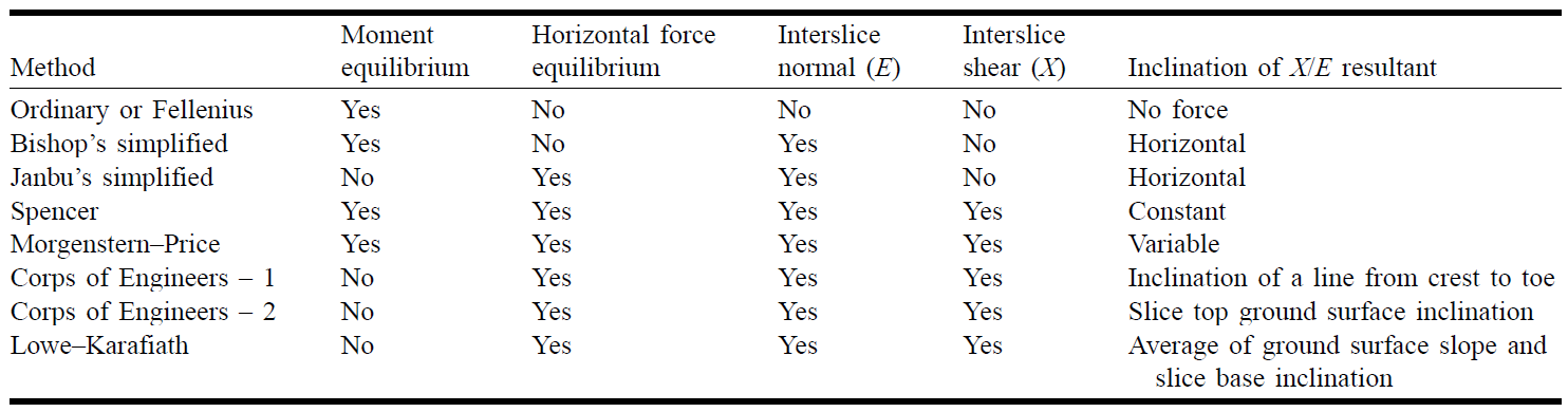 Table 1. Statics satisfied and interslice forces in various methods (click)
As mentioned before, different types of LEM methods exist differing in how they solve the problem of equilibrium of slices by statics. You can see the pros and cons of each method in this table. Bishop’s method is most widely used for slope stability analysis and is well suited for clays as cohesive materials often go through the rotational failure of mass volume about a point of rotation.
For more complex problems involving, highly heterogeneous ground with different material between adjacent layers, and where the interslice shear force is expected to vary, you can use the Morgenstern-Price method using variable functions for modeling interslice shear forces.
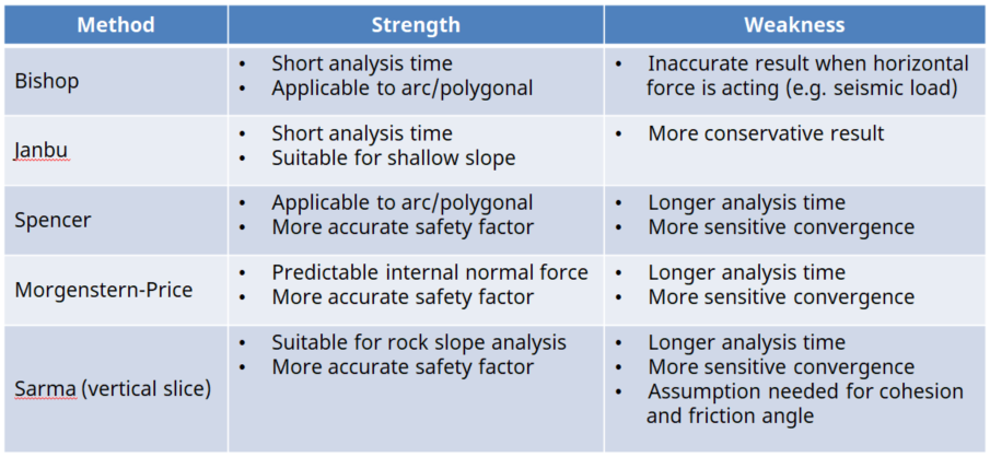 Table 2. Comparison of LEM analysis methods (click)
👇 Watch the popular case study webinar
Unsaturated Slope Stability Analysis using GTS NX
Finite Element Method (FEM)
1. Overview
The safety factor registered utilizing the LEM is not particularly decided, in light of the fact that it fluctuates with the suspicion made for the slip surface. The outcome may not be solid if nonhomogeneous and anisotropic stratifications are considered. In this manner, the better approach is to utilize limited component techniques, which process anxiety conveyance. These strategies are especially helpful for the examination of slope strength when it is liable to different sorts of stacking or when it has a complex geometry. As of late, the limited component technique has been generally utilized for snappy beginning stage slope solidness analysis. The two methodologies of strength examination, one in view of the point of confinement balance (LE) plans and the other in light of limited component (FE) standards are broadly utilized as a part of training.
This LEM are entrenched for a long time, and hence some of them are still ordinarily utilized as a part of training for dependability examination. Effortlessness and generally great outcomes are the benefits of these techniques. Since, the FEM depends on the stress‐strain relationship, push redistributions are without a doubt better processed notwithstanding for a confusing issue.
2. Strength Reduction Method (SRM)
The finite element method (FEM) with shear strength reduction technique was proposed by Zienkiewicz et al. (1975). This method is effective for assessing the performance together with the safety factor of slope and locating the failure surface that was proven by past studies. The essence of FEM with the shear strength reduction technique is the reduction of the soil strength parameters until the soil fails. The FOS produced by this method is known as the strength reduction factor (SRF).
For more details, the shear strength parameters (cohesion and internal friction angle) are gradually reduced until divergence in the solution with respect to convergence criteria such as based on displacement or force or strain energy occurs. At that point, the slope is said to have failed. The factor of safety is the ratio of initial and reduced strength parameters at failure.
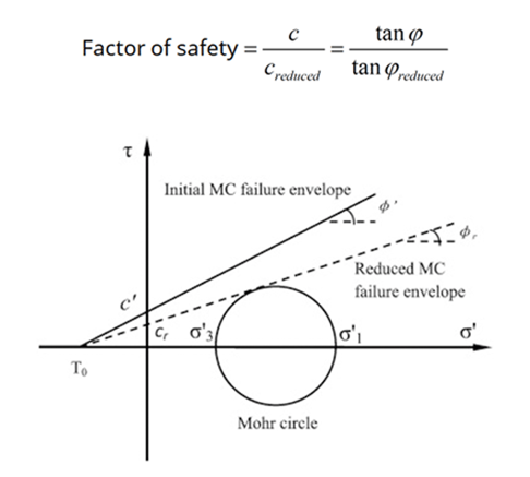
Figure 5. MC failure envelope
3. Advantages of the Finite Element Method
The advantages of a FEM to slope stability analysis over traditional LEM can be summarized as follows:
- No assumption needs to be made in advance about the shape or location of the failure surface.
- Failure occurs naturally through the zones within the soil mass in which the soil shear strength is unable to sustain the applied shear stresses.
- Since there is no concept of slices in the FE approach, there is no need for assumptions about slice side forces.
- The FEM preserves global equilibrium until failure is reached.
- If realistic soil compressibility data are available, the FE solutions will give information about deformations at working stress levels.
- The FEM is able to monitor progressive failure up to and including overall shear failure.
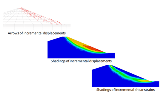
Figure 6. Different plots to check failure mechanism
Conclusions
Geotechnical limit equilibrium stability analysis techniques have limitations. The limitations arise chiefly because the method does not consider strain and displacement compatibility. This has two serious consequences. One is that local variations in safety factors cannot be considered, and the second is that the compute stress distributions are often unrealistic. To allow for variations in local safety factors along the slips surface and to deal with somewhat realistic stresses, the formulation and analysis technique needs to include a stress-strain constitutive relationship. It is the absence of a stress-strain relationship in conventional limit equilibrium analysis methods that is the fundamental piece of missing physics.
The tools required to carry out geotechnical stability analyses based on finite element computed stresses are today readily available. Applying the tools is now not only feasible but also practical. Unforeseen issues will possibly arise in the future, but such details will likely be resolved with time as the method is used more and more in geotechnical engineering practice. Using finite element computed stresses inside a limit equilibrium framework to analyze the stability of geotechnical structures is a major step forward since it overcomes many of the limitations of traditional limit equilibrium methods and yet provides an anchor to the familiarity of limit equilibrium methods so routinely used in current practice.
Following conclusions are drawn from the review of research papers of slope stability analysis:
FEM has been shown to be a reliable and robust method for assessing the factor of safety of slopes. One of the main advantages of the FEM is that the factor of safety emerges naturally from the analysis without the user having to commit to any particular form of the mechanism a priori. The FE approach for determining the factor of safety of slopes has satisfied the criteria for effective computer-aided analysis.
The factor of safety differences between the finite element method and limit equilibrium method results are small. Any failure mode develops naturally there is no need to specify a range of trail surfaces in advance. Multiple failure surfaces evolve naturally. LEM has been the primary method used in estimating the stability of slope for decades.
However, due to some of the shortcomings of LEM, the FEM is a great tool to model the non-linear stress-strain behavior of materials and understand the stability based on deformations. There is no concept of slices in the FE approach, there is no need for assumptions about slice side forces. No assumption needs to be made in advance about the shape or location of the failure surface.

🚩 Related Project Stories
- Blog | Climatic Effect on Unsaturated Slope
- Blog | Failures of Unsaturated Soil Slopes
- Blog | Possible adaptation measures related to policy in Singapore

>>Reference
- Vinod B R, P Shivananda, Swathivarma R, Bhaskar MB, "Some of Limit Equilibrium Method and Finite Element Method based Software is used in Slope Stability Analysis", International Journal of Application or Innovation in Engineering & Management (IJAIEM), Volume 6, Issue 9, September 2017, pp. 006-010, ISSN 2319 - 4847.
- Michael Duncan, Stephen G. Wright, “Soil Strength and Slope Stability” ISBN 0-471-69163-1, 2005, Published by John Wiley & Sons, Inc., Hoboken, New Jersey.
- Krishna Prasad Aryal, Doctoral Thesis, “Slope Stability Evaluations by Limit Equilibrium and Finite Element Methods”, Norwegian University of Science and Technology, April 2006.
-D. V. Griffiths, P. A. Lane, “Slope stability analysis by finite elements”, Geotechnique, Volume-3 (1999), pp. 387-403
- John Krahn. The 2001 R.M. Hardy Lecture: The limits of limit equilibrium analyses. Canadian Geotechnical Journal. 40(3): 643-660. https://doi.org/10.1139/t03-024
- Petterson, K.E. 1955. The early History of circular sliding surfaces. Geotechnique, 5: 275-296
- M. Rabie, “Comparison study between traditional and finite element method for slope under heavy rainfall”, HBRC, 2014
- Zienkiewicz, O. C., Humpheson, C. and Lewis, R. W. (1975) Associated and nonassociated visco-plasticity and plasticity in soil mechanics. Geotechnique 1975; 25(4): 671–89.
- Lane, P.A., and Griffiths, D.V. (2000) Assessment of stability of slopes under drawdown
conditions. J Geotech Geoenviron Eng, ASCE 2000; 126(5): 443–50.
- Cai, F. and Ugai, K. (2004) Numerical analysis of rainfall effects on slope stability. Int J
Geomech, ASCE 2004; 4(2): 69–78.
- Huang, M., and Jia, C. Q. (2008) Strength reduction FEM in stability analysis of soil slopes
subjected to transient unsaturated seepage. Computers and Geotechnics, 36 (2009): 93–101.