🖱️ Click to jump
1. Pile group settlement analysis
2. Midas GTS NX for geometry makers
3. Comparison between full-scale model and simplified model
👇 Now Register | FEM Analysis for Underground Mine Stability
Pile group settlement Analysis
The settlement behavior of a pile group has long been known to differ from the settlement of a single pile. A number of methods have been proposed to estimate the settlement of pile groups. Some of the methods give the maximum total settlement of pile group (refer as type A) while some other methods have capabilities to determine settlement distribution (refer as type B). The equivalent raft method (Poulos 1993; Terzaghi and Peck 1948; Tomlinson 1977) is one of the most famous methods to determine the settlement of pile groups that falls under type A. Other empirical methods that are employed for the settlement of shallow foundations (De Beer and Martens 1957; Schmertmann 1970) can also be used to determine the settlement of the pile group by assuming that the pile group can be replaced with an equivalent raft located at the specific depth below cut off level.
Poulos's pile interaction method (Poulos 1968; Poulos and Mattes 1971; Poulos and Davis 1980) has capabilities of determining settlement distribution beneath the construction. However, the pile interaction method is limited to a single homogeneous soil layer which is rarely encountered.
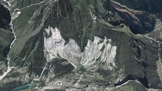
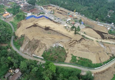
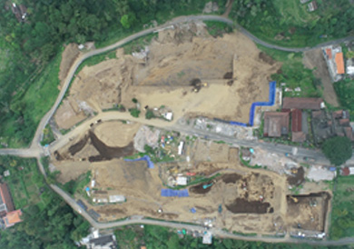
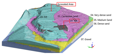
Due to the recent development in construction technologies, it is no longer rare for a building to be constructed on top of a mountain which involves a number of cut and fill processes as shown in Figure 1. Based on the in‑situ test conducted at the site, the soil layer is non-uniform as indicated in Figure 2. Hence, the analysis becomes very complicated when the construction process, soil surface geometry, and non‑horizontal soil layers are considered.
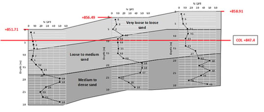 Figure 2_ Soil Layer at the site
midas GTS NX for Geometry Maker
Geometry construction becomes one of the main challenges for conducting 3D analysis. Several methods that can be used in MIDAS to help constructing the geometry is as follow:
1. Terrain Geometry Maker (TGM)
2. Bedding Plane
3. Divide Mesh
Terrain geometry maker (TGM) is one of the powerful add ins in MIDAS GTS NX which has the capabilities to convert contour line into a surface as shown in Figure 3. Combining TGM with other third party software which has capabilities to conduct spatial interpolation and obtaining contour line, it is possible to construct Surface layer, phreatic surface and also soil layering into the GTS NX.
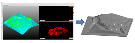 Figure 3_ Terrain geometry maker (TGM)
When third party software is not available, it is possible to use bedding plane (Figure 4) to conduct spatial interpolation and hence obtaining soil surface to soil layers. Bedding plane makes it convenient to import soil layer from boreholes for 3D analysis purposes. However, it is sometimes difficult to control spatial interpolation and hence additional dummy or control points are required to ensure the soil layer is according to the user desired.
While geometry appears to be successfully made, it is sometimes difficult to ensure that the geometry can be meshed. Very complicated geometry or layering might also cause very small or distorted mesh which has aspect ratio problems. Hence, another strategy that can be employed is to use divide mesh (Figure 5). By using divide mesh, it is possible to separate a mesh set into 2 mesh sets by using a surface. Hence, different soil layer can thus be assigned by changing the properties of the divided mesh. However, the problem with divide mesh is that the interface between 2 mesh set might not be smooth. Hence, mesh must be sufficiently small in order to ensure that the divided mesh can be representative.
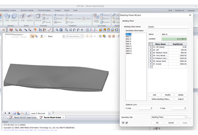 Figure 4_ Bedding Plane Wizard
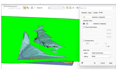 Figure 5_ Divide Mesh Set
Comparison between Full Scale Model and Simplified Model
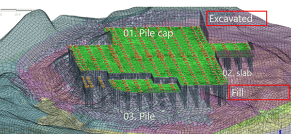
Settlement analysis is commonly conducted without considering the soil surface layer or the staging construction. For comparison, two models are provided. In the first model (Figure 6), soil surface made from the contour is modelled. Cut and fill construction is also considered in the model.
a) Before construction
b) After construction
Figure 6_ Model A
In the second model (Figure 7), the soil layer is horizontal, cut and fill construction is also ignored. Figure 8 shows the comparison between the two models.
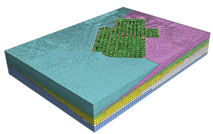 Figure 7_ Model B
In Model A, excavated area is subjected to smaller settlement as the soil located at the excavated area is subjected to stress release due to excavation process (OCR >1). On the other hand, in Model B the settlement does not consider stress release and hence higher settlement occurs. Settlement profile in Model B solely controls by the distribution of column load and hence does not consider the change in stress state due to cut and fill construction process.
%20Settlement%20for%20Model%20B.jpg?width=567&name=Figure%208-1_Comparison%20bewtween%20settlement%20profile%20-%20a)%20Settlement%20for%20Model%20B.jpg) a) Settlement for Model A
a) Settlement for Model A_Settlement%20for%20Model%20B.jpg?width=557&name=Figure%208_Comparison%20bewtween%20settlement%20profile%20-%20a)_Settlement%20for%20Model%20B.jpg)
b) Settlement for Model B
Figure 8_ Comparison between settlement profiles for Model A and B
Conclusion
Challenges in conducting 3D settlement analysis mostly consist of constructing proper 3D geometry. In order to help the user in constructing a proper 3D model, MIDAS GTS NX provides several useful tools such as terrain geometry maker (TGM), bedding plane, and divide mesh. It provides flexibility for the user to decide which method suits them best for their problem.

⭐ Recommendation (Click)
- Blog | Numerical Analysis of Tunnels in Anisotropic Formations - Continuum and Discontinuum Approaches
- Blog | Design Tips For Retaining Walls In Excavation Works
- Blog | The Advantages Of 3D Analysis In Major Fields
👇 Register Now | FEM Analysis for Underground Mine Stability
Reference
- De Beer, E., and Martens, A. Method of Computation of an Upper Limit for an Influence of the Heterogeneity of Sand Layers on the Settlements of Bridges. In Proceedings of the 4th ICSMFE. London 1957. pp. 275-282.
- Poulos, H.G. 1968. Analysis of the Settlement of Pile Groups. Geotechnique, 18(4): 449-471.
- Poulos, H.G. Settlement prediction for bored pile groups. In Proc. 2nd Geotechnical Seminar on Deep Foundations on Bored and Auger Piles. Ghent 1993. pp. 103-117.
- Poulos, H.G., and Mattes, N.S. 1971. Settlement and Load distribution Analysis of Pile Groups. Australian Geotechnical Journal, G1: 18-28.
- Poulos, H.G., and Davis, E.H. 1980. Pile Foundation Analysis and Design.
- Schmertmann, J.H. 1970. Static Cone to Compute Static Settlement Over Sand. Journal of Soil Mechanics and Foundation Division, ASCE, 96(3): 1011-1043.
- Terzaghi, K., and Peck, R.B. 1948. Soil Mechanics in Engineering Practice. John Wiley and Sons, New York. pp. 566.
- Tomlinson, M.J. 1977. Pile Design and Construction Practice. In Viewpoint Publications, London.